Electrical Installation
Eaton 9355 UPS (20/30kVA) Installation and Operation Manual 164201626—Rev F www.eaton.com/powerquality 25
Parallel UPS Wiring
To hardwire the UPS in a parallel capacity and/or redundant system:
1. Remove the UPS conduit landing box from the rear panel and retain (see Figure 14).
2. Punch two holes in the conduit landing box for the input and output conduit using a Greenlee punch or
similar device.
3. Route the wiring from the back of the UPS, through the wiring tray, to the front of the UPS.
4. Hardwire the input terminations for the UPS. See Table 1 on page 35 for wiring specifications.
For a detailed view of the UPS terminal block, see Figure 23 on page 36. See Figure 15 or Figure 16 for a
parallel wiring diagram.
5. Remove any Tie Cabinet covers and install conduit for the Tie Cabinet.
6. Hardwire the output terminations from the UPS to the Tie Cabinet.
7. Hardwire the load to the Tie Cabinet.
8. Wire the maintenance bypass auxiliary contacts below the maintenance bypass switch and terminate to
the maintenance bypass wires in the Tie Cabinet.
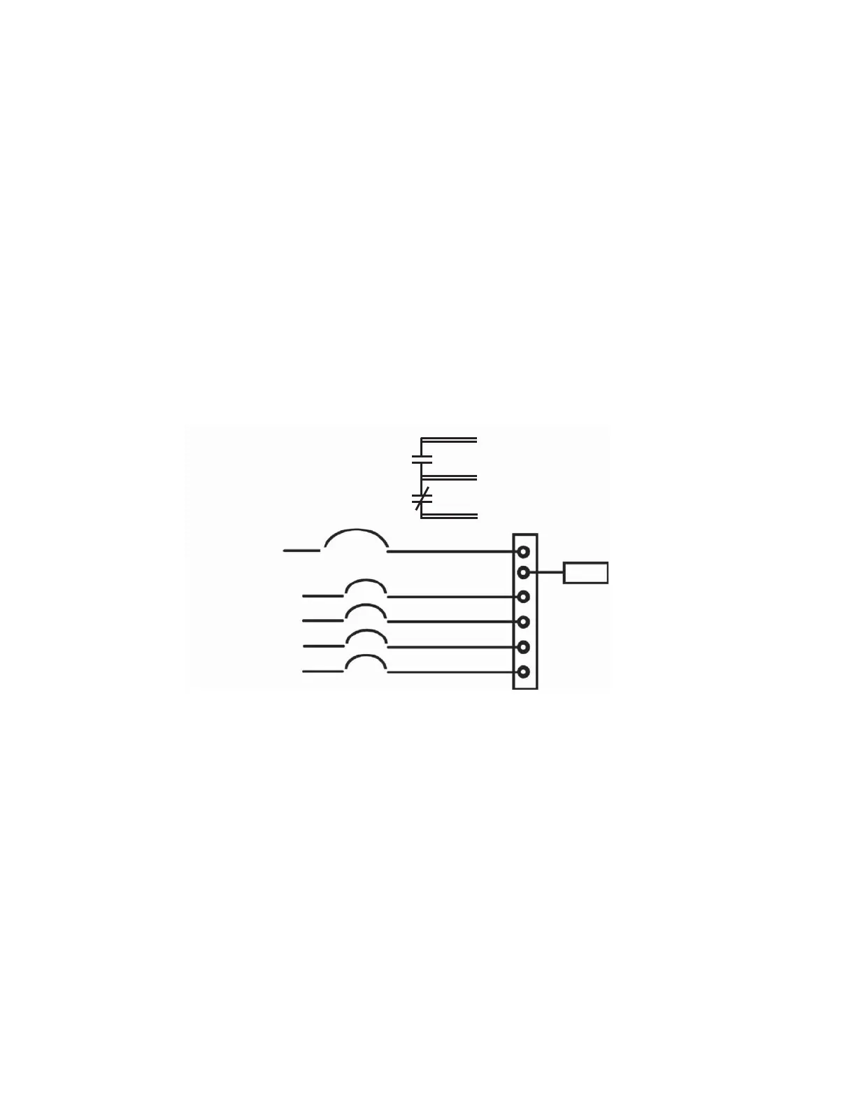
Figure 15. Parallel Wiring Diagram – Version 1 and Version 2 without Maitenance Isolation Switch (MIS)
From UPS 4 Output
From UPS 3 Output
From UPS 2 Output
Red Wires
(open when breaker is open)
Bypass Input
Black
Wires
(common)
From UPS 1 Output
350A
110A (4X)
LOAD
Blue Wires
(closed when breaker is
open)
350A Breaker
Auxiliary Contacts

 Loading...


