Communication
52 Eaton 9355 UPS (20/30kVA) Installation and Operation Manual 164201626—Rev F www.eaton.com/powerquality
Installing Communication Options and Control Terminals
Note: To install a CAN Bridge Card, see “Parallel Communication” on page 63.
To access and install the communication options and control terminals:
1. Remove the UPS front door (see page 10).
2. Install the appropriate X-Slot card and/or necessary cables into the ports (see Figure 36 and Figure 37).
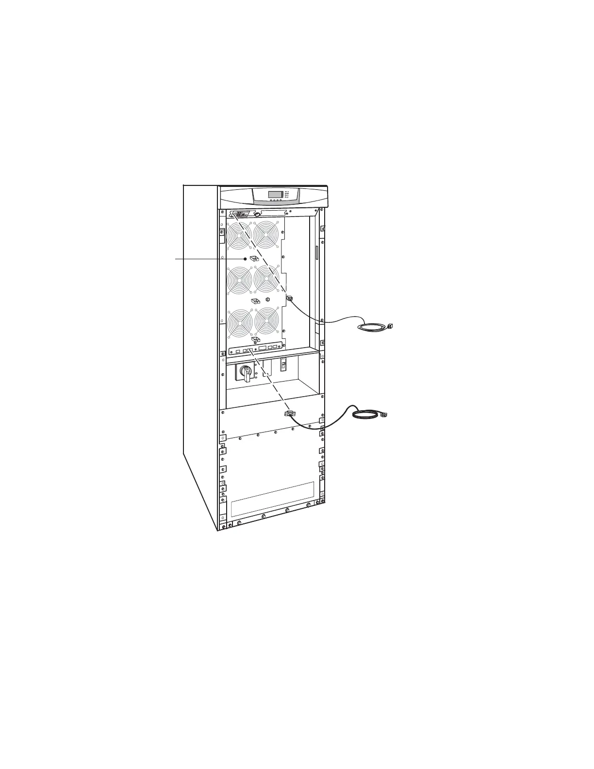
3. Route the control terminal cable(s) through the middle of the fan section and secure in the cable clips.
Figure 37. Installing Communication Cables
Cable Clips for Control
Terminal Wiring

 Loading...


