5 Structure
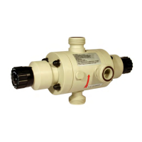
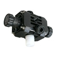
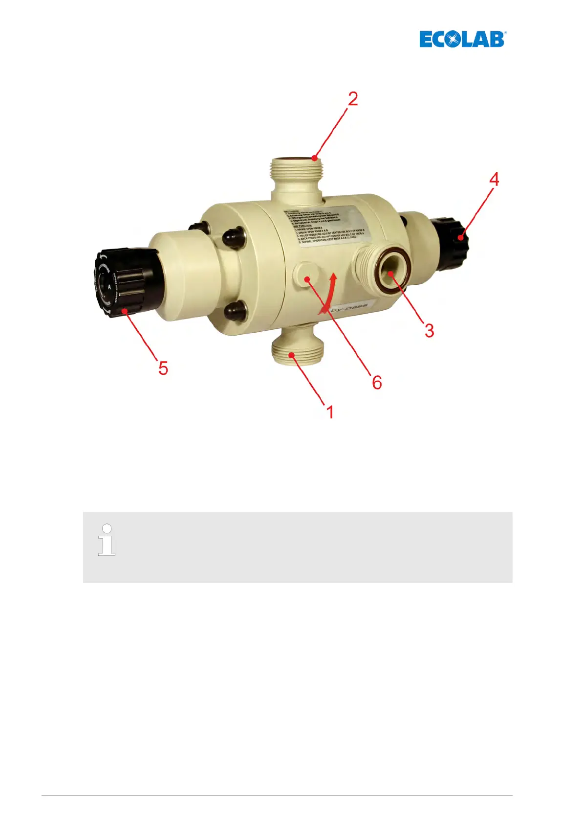
Fig. 1: Structure
1 Valve inlet (from metering pump)
2 Valve outlet (to metering line)
3 Bypass connection (to tank)
4 Overpressure: Venting / drainage (Adjustment Knob
"B"),
Ä
on page 28
5 Pressure maintenance side: Discharge (Adjustment
Knob "A"),
Ä
on page 29
6 Pressure-gauge connection, G ¼" (blanked off with a
plug in as-delivered condition)
The O-rings for the following connections are included in the scope of
supply: Inlet (Item 1), Outlet (Item 2) and Bypass (Item 3).
We recommend the use of a pressure gauge to permit read-off of the
counterpressure set (
Ä
Chapter 10.2.4 ‘Pressure gauge’ on page 38).
Structure
22417101434 Rev. 5-05.2019
 Loading...