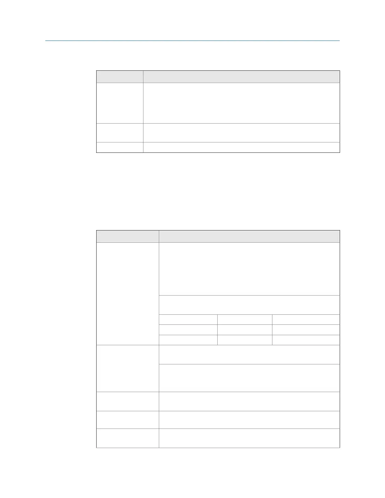
General settings (continued)Table 1-1:
Setting Description
Mounting
The
display may be mounted directly to conduit by using slotted flanges for
wall mounting or NPS 1½" to 2½" or DN 40 to 65 mm pipe mounting. Note:
Certain sequences of events can cause unexpected results. To avoid unexpec-
ted issues, use factory defaults and anticipate the possibility of changes in the
mounting strategy.
Overall dimen-
sions
(144 mm x 133 mm x 124 mm)
5.67" x 5.24" x 4.88" (W x H x D)
Weight 5.00 lbs (80 oz, 2.27 kg)
1.3 Rate input settings
The settings below are rate input specifications for the Internal Display. Except when
noted, all specifications apply to operation at +25°C (+77°F).
Rate input settingsTable 1-2:
Setting Description
Pulse/ transistor/ con-
tact closure input
Field selectable; Sourcing or sinking pulse or square wave 0-5 V, 0-12 V,
or 0-24 V; TTL; NPN or PNP transistor
Open collector 100 kΩ pull-up to 3 V
Switch contact 100 kΩ pull-up to 3 V
PNP transistor 100 kΩ pull-down to ground (COM)
Active input 100 kΩ to battery level, 10 kΩ to power
Maximum Frequency: 64 kHz
Minimum Pulse Width: 5 μs
Threshold Setting Low (V) High (V)
Normal 1.2 1.8
Low 0.2 1.0
Opto-isolated input Sourcing pulse or square wave 0-5 V, 0-12 V, or 0-24 V
Logic High: 2-24 V, Logic Low: < 1 V
Maximum Frequency: 20 kHz
Minimum Pulse Width: 20 μs
Input Current: 1 mA @ 5 V, 2.5 mA @ 12 V, 5 mA @ 24 V
Low voltage mag pick-
up input
Sensitivity: 20 mVp-p to 24 Vp-p
Maximum Frequency: 6 kHz
Minimum input fre-
quency
0.001 Hz. Minimum frequency is dependent on high gate setting (rate
display).
Input impedance Pulse input: Greater than 75 kΩ @ 1 kHz.
Open collector/switch input: 100 kΩ pull-up to 3 V.
Introduction
6 LTM Internal Display
 Loading...


