Chapter 3 Installation and Wiring 17
EV2000 Series Universal Variable Speed Drive User Manual
3.3 Wire Connections of Drive
Danger
!
·Wiring can only be done after the drive’s AC power is cut
off and all the LEDs on the operation panel are off. Wait for
at least 5mins before removing the panel.
·Wiring can only be done after confirming the charge
indicator on the right bottom is off and the voltage between
main circuit power terminals + and - is below DC36V.
·Wire connections can only be done by trained and
authorized personnel.
·Check the wiring carefully before connecting emergency
stopping or safety circuits.
·Check the drive’s voltage level before supplying power to
it, or human injuries and equipment damage may happen.
Attention
!
·Ensure that the drive’s rated input voltage is in compliant
with the AC supply voltage before using it.
·Dielectric strength test of the drive has been done in
factory, so you need not do it again.
·See chapter 2 on connected braking resistor or braking kit.
·It is prohibited to connect the AC supply cables to the
drive’s terminals U, V and W.
·Grounding cables should be copper cables with section
area bigger than 3.5mm
2
, and the grounding resistance
should be less than 10Ω.
·Leakage current exists in the drive. The total leakage
current is bigger than 3.5mA, depending on the usage
conditions. To ensure safety, the drive and the motor should
be grounded, and a leakage current protector (RCD) should
be used. It is recommended to choose B type RCD and set
the leakage current at 300mA.
·The drive should be connected to the AC supply via a
circuit breaker or fuse to provide input over-current
protection or convenience for disconnecting the AC supply
to maintain the drive.
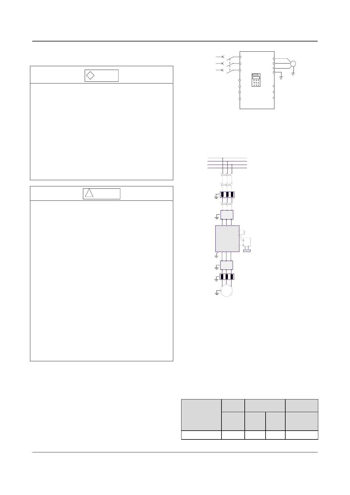
Wire the drive according to Fig. 3-7 during
commissioning:
EV2000
U
V
W
PE
M
R
S
T
3-phase
AC
supply
QF
VRF
VCI
GND
FWD
COM
.
.
.
.
.
.
CCI
REV
.
Fig. 3-7 Wiring
3.3.1 Wire Connections of Main Terminals
1. Connection between drive and optional parts
IM
AC input reactor
AC output reactor
Input EMI filter
Output EMI filter
Circuit breaker or
fuse
Contactor
DC reactor
PE
U
V
W
EV2000
R S T
+
-
P1
Braking unit
Braking resistor
M
R
Isolator switch
N
S
T
Fig. 3-8 Wire connection between the drive and optional parts
1). Isolation switch should be connected between the AC
supply and the drive to ensure the safety of the
maintenance engineer.
2). Circuit breaker (QF) or fuse should be connected
between the AC supply and the drive to isolate the fault of
other equipment. Refer to Table 3-1 for the selection of
circuit breaker.
3) When a contactor is used for controlling the AC supply,
don’t use it to switch on or off the Variable Speed Drive.
Table 3-1 Recommended capacity of circuit breaker and
the cross sectional area of copper cable
Model
EV2000-4T
Input
switch
Main circuit
(mm
2
)
Control circuit
(mm
2
)
Circuit
breaker
QF(A)
Input
cable
Output
cable
Control
terminal
0055G/0075P 32 4 4 1
 Loading...


