Chapter 5 Parameter Introductions 69
EV2000 Series Universal Variable Speed Drive User Manual
Binary settings Hex value
(Displaying of LED)
Bit3 Bit2 Bit1 Bit0
1 0 1 0 A
1 0 1 1 B
1 1 0 0 C
1 1 0 1 D
1 1 1 0 E
1 1 1 1 F
Note:
Factory setting of all the terminals is positive logic.
5.9 Display (Group F8)
F8.00 Language selection
Range:0~1【0】
0:Chinese
1:English
F8.00 is effective for the panel with LCD screen.
F8.01 Displayed parameter
group 1 during operation
Range:000~3FFH
【3FFH】
A
B
C
D
BIT0: output freq. Hz
(before compensation)
BIT1: output freq. Hz
(after compensation)
BIT2: preset freq.
Hz
BIT3: output current A
BIT0 : running speed
rpm
BIT1: preset speed rpm
BIT2: running line speed m/s
BIT3: preset line speed m/s
BIT0: output power
BIT1: output torque
%
BIT2: reserved
BIT3: reserved
BIT0: reserved
BIT1: reserved
BIT2: reserved
BIT3: reserved
Fig. 5-52 LED displayed parameter group 1 in operation
Where,
A: thousand’s place B: Hundred’s place
C: Ten’s place D: Unit’s place
F8.01 and F8.02 define the parameters that can be
displayed by LED in operating status.
If Bit is 0, the parameter will not be displayed;
If Bit is 1, the parameter will be displayed.
For example, Unit place of LED (Bit0) is to display the
“output frequency before compensation”, if Bit0=0, the
parameter will not be displayed, if Bit0=1, the parameter
will be displayed.
See F7.35 for the relationship between the values of
each Bit and the displayed value of LED.
F8.02 Displayed parameter
group 2 during operation
Range:000~3FFH
【000H】
A
B
C
D
BIT0: output volt V
BIT1: DC bus volt
V
BIT2: VCI V
BIT3: CCI V
BIT0: closeloop feedback
%
BIT1: closeloop reference%
BIT2: external counting value
BIT3: terminal status
BIT0
: actual length
BIT1: preset length
BIT2: reserved
BIT3: reserved
BIT0: reserved
BIT1: reserved
BIT2: reserved
BIT3: reserved
Fig. 5-53 Operating parameter 2 displayed by LED
Where,
A: thousand’s place B: Hundred’s place
C: Ten’s place D: Unit’s place
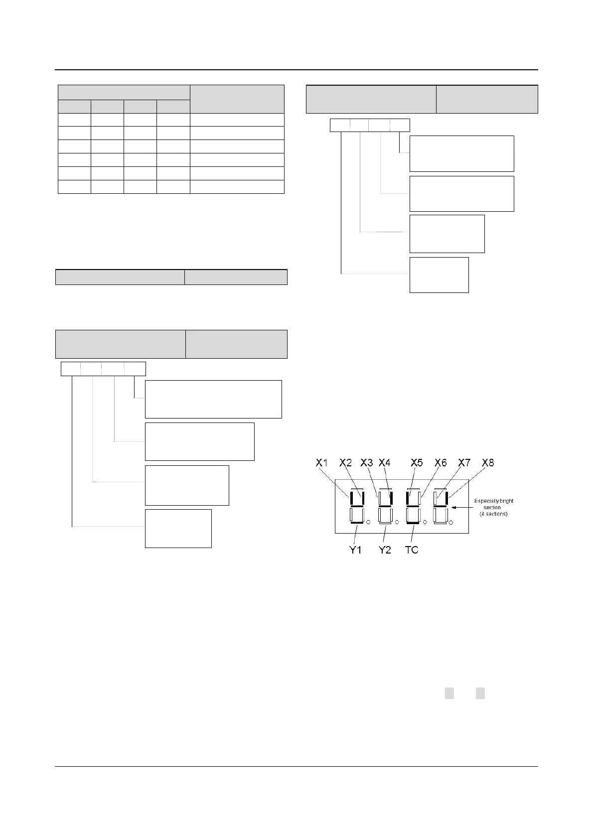
The terminal information includes status of terminal
X1~X8, bi-direction open-collector output terminals Y1
and Y2, and relay output terminal TC. The status of
terminals are indicated by the “On” or “Off’ of LED. If the
LED turns on, that means the terminal is enabled, and
the terminal is disabled if the LED turns off, as shown in
Fig.5-54:
Fig. 5-54 Terminal status
In Fig.5-54, the LEDs display that terminals X1, X2, X4,
X5 and X8 are enabled, terminals X3, X6 and X7 are
disabled, terminals Y1 and TC are enabled and terminal
Y2 is disabled. The central four LEDs always illuminate
for the convenience of observation.
Note:
When the rotating speed and line speed are displayed, these
values can be revised by pressing ▲ and ▼ directly (no
need to switch to frequency displaying status).
When F8.01 and F8.02 are all set to 0, the frequency before
compensation will be displayed.
 Loading...


