Chapter 3 Installation and Wiring 31
EV2000 Series Universal Variable Speed Drive User Manual
+24V
EV2000
P24
4.7K
DO
COM
+5V
+24V
Digital
frequency
meter
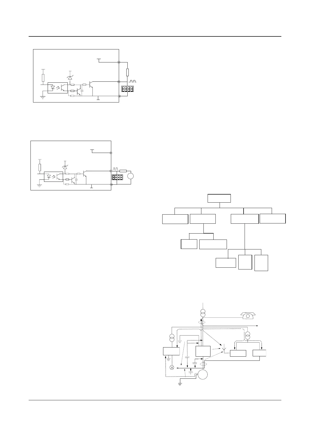
Fig. 3-30 Wiring 1 of output terminal DO
④Pulse output terminal DO can also use the external
9~30V power supply and the wiring is shown in Fig.3-31.
+24V
EV2000
P24
4.7K
DO
COM
+5V
+24V
Digital frequency
meter
~
9 30V
+
-
Fig. 3-31 Wiring 2 of output terminal DO
3) Wiring relay output terminals TA, TB and TC.
If the drive drives an inductive load (such as relay or
contactor), then a surge suppressing circuit should be
added, such as RC snub circuit (pay attention that the
leakage current must be smaller than the holding current
of the controlled relay or contactor) and varistor or a
free-wheeling diode (used in the DC electric-magnetic
circuit and pay attention to the polarity during
installation). Snubbing components should be as close
to the coils of relay or contactor as possible.
Notes:
1. Don’t short circuit terminals P24 and COM, otherwise
the control board may be damaged.
2. Please use multi-core shielded cable or multi-stranded
cable(above 1mm) to connect the control terminals.
3. When using a shielded cable, the shielded layer’s end
that is nearer to the drive should be connected to PE.
4. The control cables should be as far away(at least 20cm)
from the main circuits and high voltage cables as possible
(including power supply cables, motor cables, relay cables
and cables of contactor). The cables should be vertical to
each other to reduce the disturbance to minimum.
5. The resistors R in Fig. 3-27 and Fig.3-28 should be
removed for 24V input relays, and the resistance of R
should be selected according the parameters of relay for
non-24V relay.
3.4 Installation Methods Compliant With
EMC Requirements
The drive inevitably generates noise due to its high
switching frequency, so relevant EMC problems must be
solved so as to reduce the drive’s disturbance to
external equipment. This chapter deals with the
installation methods compliant with EMC requirements
from the aspects of noise suppression, field wiring,
grounding, leakage current and the using of power filter.
This chapter can be used as a reference for field
installation.
3.4.1 Noise Suppressing
The noise generated by the drive may disturb the
equipment nearby. The degree of disturbance is
dependent on the drive system, immunity of the
equipment, wiring, installation clearance and earthing
methods.
1. Noise categories
Route⑥
...
Route⑤
...
Route④
...
ESD induction
Noise
Route
①
...
Electro-magnetic
induction noise
Route ,
⑦⑧
...
Transmission noise
of power cables
Earthing
noise
Conduction noise
Route③
...
Route②
...
Noise
Ttransmission noise
in space
Radiation noise
of motor
Radiation
noise
of power
cables
Radiation
noise
of power
cables
Fig. 3-32 Noise categories
2. Noise propagation paths
D
r
i
v
e
R
a
d
i
o
⑧
⑤
⑥
④
③
③
④
⑦
②
①
⑤
Sensor
Motor
Sensor's
power supply
Phone
M
e
t
e
r
Fig. 3-33 Noise transmission paths
 Loading...


