Chapter 5 Parameter Introductions 77
EV2000 Series Universal Variable Speed Drive User Manual
FWD, REV, YI, Y2 and TC respectively. Please refer to
Table A-8 of Appendix 3. The actual terminal is disabled
if the virtual terminal is enabled. The virtual terminal is
equivalent to the actual terminal.
The setting of thousand’s Bit does not affect the
communication process. If FF.00 is set to MODEM
(RS232) mode, the MODEM will be initialized via the
RS232 port each time when the drive is switched on, so
that the MODEM can answer the call automatically after
it receives 3 ringing signals. See section 3.3.2 in chapter
for the wiring of remote control circuit formed by dialed
circuits.
FF.01 Local address
Range:0~127【1】
In serial communication, FF.01 is used to identify the
drive’s address.
Note: “127” is the broadcast address. When the address
is set to broadcast address, the drive can receive and
execute the command sent by control PC, but will not
answer the PC.
FF.02 Time threshold for judging
communication status
Range:0~1000.0s
【0.0s】
If the drive has not detected the communication signal
from the serial port for certain time, it will judge that
communication failure occurs. The time threshold is
defined by FF.02.
If FF.02 is set to 0, the drive will not detect the
communication signal of serial port and this function is
disabled.
FF.03 Host PC response
delay
Range:0~1000ms【5ms】
It refers to the time from drive receiving the host PC
command to returning response frame to it.
5.13 Motor Parameters (Group FH)
FH.00 Number of
polarities of motor
Range: 2~14【4】
FH.01 Rated power
Range:0.4~999.9kW【dependent
on drive’s model】
FH.02 Rated current
Range:0.1~999.9A 【dependent
on drive’s model】
FH.00, FH.01 and FH.02 are used to set the motor’s
parameters.
In order to ensure the control performance, please set
FH.00~FH.02 with reference to the values on the
motor’s nameplate.
Note:
The motor’s power should match that of the drive.
Generally the motor’s power is allowed to be lower than
that of the drive by 20% or bigger by 10%, otherwise the
control performance cannot be ensured.
FH.03 Current without
load I0
Range:0.1~999.9A【dependent
on drive’s model】
FH.04 Resistance of
stator %R1
Range:0.0~50.00%【dependent
on drive’s model】
FH.05 Leakage
inductance %Xl
Range:0.0~50.00%【dependent
on drive’s model】
FH.06 Resistance of
rotor %R2
Range:0.0~50.00%【dependent
on drive’s model】
FH.07 Exciting
inductance %Xm
Range:0.0~2000.0%【dependent
on drive’s model】
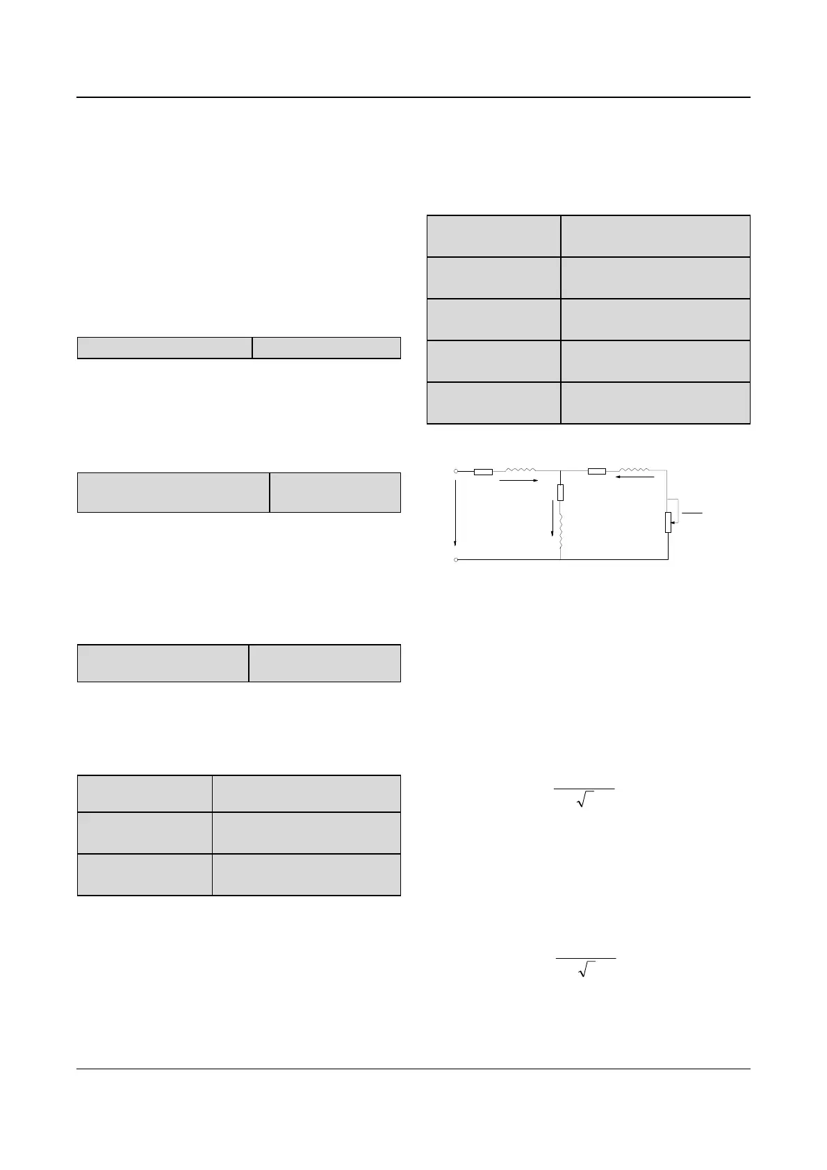
See Fig. 5-70 for the above parameters.
R
m
X
m
I
0
I
1
U
1
R
1
jX
1l
R
2
jX
2l
1-S
S
R
2
I
2
Fig. 5-70 Motor’s equivalent circuit
In Fig. 5-70, R
1
, X
1l
, R
2
, X
2l
, X
m
and I
0
represent stator’s
resistance, stator’s leakage inductance, rotor’s
resistance, rotor’s leakage inductance, exciting
inductance and current without load respectively. The
setting of FH.05 is the sum of stator’s leakage
inductance and rotor’s inductance.
The settings of FH.04 ~FH.07 are all percentage values
calculated by the formula below:
()
%100
3/
% ×
⋅
=
IV
R
R
R: Stator’s resistance or rotor’s resistance that is
converted to the rotor’s side;
V: Rated voltage;
I: Motor’s rated current
Formula used for calculating inducatance (leakage
inductance or exciting inductance):
()
%100
3/
% ×
⋅
=
IV
X
X
X: sum of rotor’s leakage inductance and stator’s
leakage inductance (converted to stator’s side)or the
exciting inductance based on base frequency;
 Loading...


