34 Chapter 3 Installation and Wiring
EV2000 Series Universal Variable Speed Drive User Manual
high frequency terminal. The paints on the bolt should
be cleaned.
The earthing cable should be as short as possible, that
is, the earthing point should be as close to the drive as
possible.
Earthing cables should be as far away from the I/O
cables of the equipment that is sensitive to noise, and
also should be as short as possible.
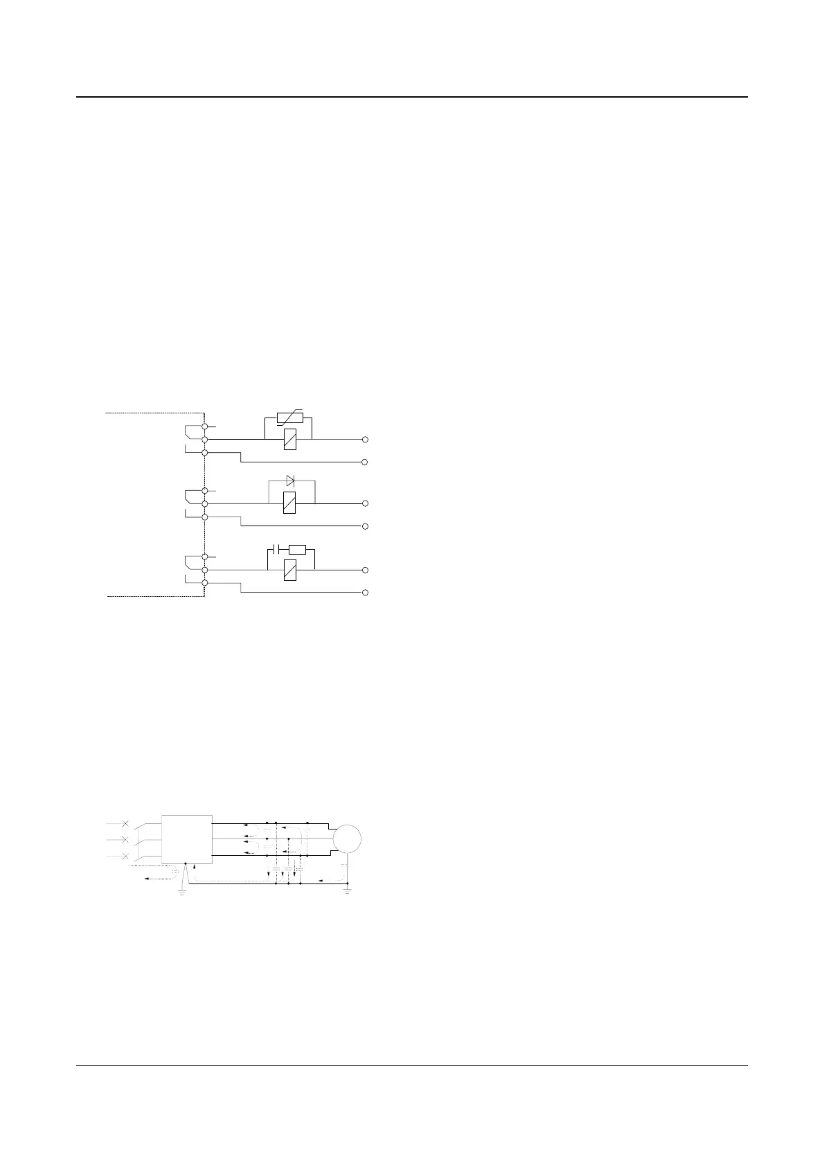
3.4.4 Installation Requirements of Relay, Contactor and
Electro-magnetic Braking Kit
The devices such as relay, contactor and
electro-magnetic braking kit, which may generate great
noises, should be installed outside of the drive cabinet
and should be installed with surge suppressors.
220VAC
Varistor
Diode
Inverter
220VAC
RC-Filter
+24VDC
Fig. 3-41 Relay, contactor and electro-magnetic braking kit
3.4.5 Leakage Current
Leakage current may flow through the drive’s input and
output capacitors and the motor’s capacitor. The
leakage current value is dependent on the distributed
capacitance and carrier wave frequency. The leakage
current includes ground leakage current and the leakage
current between lines.
AC supply
Drive
Distributed
capacitor
between lines
Motor
Distributed
capacitor between
cable and earth
Capacitor
between
motor and
earth
R
S
T
QF
Fig. 3-42 Flowing path of leakage current
Ground leakage current
The ground leakage current can not only flow into the
drive system, but also other equipment via earthing
cables. It may cause the leakage current circuit breaker
and relays falsely activated. The higher the drive’s
carrier wave frequency, the bigger the leakage current,
also, the longer the motor cable, the greater the leakage
current,
Suppressing methods:
Reduce the carrier wave frequency, but the motor noise
may be louder;
Motor cables should be as short as possible;
The drive and other equipment should use leakage
current circuit breaker designed for protecting the
product against high-order harmonics/surge leakage
current;
Leakage current between lines
The line leakage current flowing through the distribution
capacitors of the drive out side may cause the thermal
relay falsely activated, especially for the drive whose
power is lower than 7.5kW. When the cable is longer
than 50m, the ratio of leakage current to motor rated
current may be increased that can cause the wrong
action of external thermal relay very easily.
Suppressing methods:
Reduce the carrier wave frequency, but the motor noise
may become louder;
Install reactor at the output side of the drive.
In order to protect the motor reliably, it is recommended
to use a temperature sensor to detect the motor’s
temperature, and use the drive’s over-load protection
device(electronic thermal relay) instead of an external
thermal relay.
3.4.6 Correct EMC Installation
Divide the installation space into different areas
In driving system, the drive, control equipment and
sensors are installed in the same cabinet, the noise
should be suppressed at the main connecting points
with the RFI filter and input reactor installed in cabinet to
satisfy the EMC requirements.
The most effective but expensive measure to reduce the
interference is to isolate the noise source and the noise
receiver, which should be considered in
mechanical/system design phase. In driving system, the
noise source can be drive, brake unit and contactor.
Noise receiver can be automation equipment, coder and
sensor.
The mechanical/system is divided into different EMC
area according to its electrical characteristics. The
recommended installation positions are shown in the
following figure:
 Loading...


