40 Chapter 4 Operation Instructions
EV2000 Series Universal Variable Speed Drive User Manual
Table 4-2 Functions of status indicators
Indicator
Display
status
Current status of the
drive
Operating status
indicator
Off Stopping status
On Operating status
Control mode
indicator
On Panel control status
Off
Terminal control
status
Flash
Serial port control
status
4.2.4 Display of the Drive
EV2000 operation panel can display the parameters in
stopping, operating, editing and alarming state.
1. Parameters displayed in stopping status
When the drive stops operation, the panel will display
the status parameters in stopping status, as shown in
Fig. 4-4b. The unit indicator on the top right of the panel
indicates the unit of the parameter.
Other parameters can be displayed by pressing XX key
(see F8.03).
2. Parameters displayed in operating status
When the drive receives operating command, it starts
running and its panel will display the status parameters
in operating status, as shown in Fig.c of Fig. 4-4. The
unit indicator at right indicates the unit of the parameter.
Other parameters can be displayed by pressing XX key
(see F8.01 and F8.02).
UNIT
HZ
r/min
A
V
m/s
%
PARAMETER
UNIT
HZ
r/min
A
V
m/s
%
PARAMETER
EV2000
ENYDRIVE
UNIT
HZ
r/min
A
V
m/s
%
PARAMETER
ENTER
PANEL
▲
RUN
JOG
STOP
RESET
MENU
ESC
PANEL
▲
RUN
JOG
STOP
RESET
MENU
▲
RUN
STOP
RESET
ENTER
DATA
PANEL
JOG
MENU
ESC
UNIT
HZ
r/min
A
V
m/s
%
PARAMETER
UNIT
HZ
r/min
A
V
m/s
%
PARAMETER
EV2000
ENYDRIVE
Fig. a
UNIT
HZ
r/min
A
V
m/s
%
PARAMETER
ENTER
PANEL
RUN
STOP
RESET
MENU
DATA
PANELPANEL
RUN
RUN
STOP
RESET
STOP
RESET
MENUMENU
RUN
STOP
RESET
ENTER
REMOTE
RUN
RUN
STOP
RESET
STOP
RESET
ESC
RUN
RUN
STOP
RESET
STOP
RESET
▲
XX
Initialize at power on,
all LED turns on
Fig. b
Stopping state, Stopping
information is displayed ;
RUN indicator turns off
Preset frequency
Stop
Freq.
precompensation
Common run
Forward
Fig. c
Running state, running
information is displayed;
RUN indicator turns on
▲
REMOTE
XX
REMOTE
▲
XX
DATA
Fig. 4-4 Displayed during initialization, STOP, operation
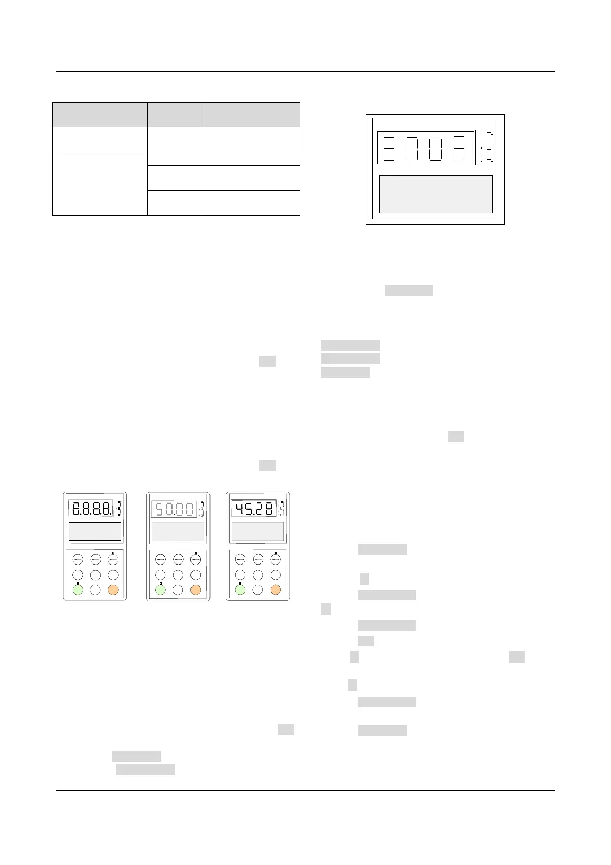
3. Alarm information
When the drive detects a fault signal, the panel will
display the fault code. The code will flash to catch your
attention as shown in Fig. 4-5;
Reference frequency can be viewed by pressing the XX
key in stopping status. Fault information can be queried
by pressing MENU/ESC key. The drive can be reset by
pressing the STOP/RESET key, or sending the reset
commands via the control terminal X2 or serial port. The
fault code will not disappear until the fault is cleared.
UNIT
HZ
r/min
A
V
m/s
%
PARAMETER
Input Phase Failure
Pls Check
Hz
Fig. 4-5 Alarm displaying status
4. Parameter configuration
When the drive is in stopping, operating or alarming
state, pressing MENU/ESC can enter configuring status,.
Configuring status can be displayed in 3-level menu,
they are: parameter group
→pparameter→parameter
value. You can enter the sub-menus by pressing
ENTER/DATA. In parameter value menu, press
ENTER/DATA to save the settings, and press
MENU/ESC to exit the menu.
4.2.5 Panel Operation
1. Viewing Parameters
To view the parameters, press XX key. The parameters
that can be displayed are different depending on the
operation state (STOP, operating) and the settings of
F8.01~F8.03)
2. Parameter Setup
Let’s look at an example of how to set parameters.
Suppose you want to change the setting of F3.13 from
5.00Hz to 6.50Hz.
1. Press MENU/ESC key to enter programming state,
the LED displays F0.
2. Press ▲ key until “F3” is displayed.
3. Press ENTER/DATA key, you will see F3.00. Press
▲ key until “F3.13” is displayed.
4. Press ENTER/DATA key, you will see “05.00”.
5. Press XXkey, to move the cursor to the digit “5”.
Press ▲ key once, to change it to “6”. Press XXkey, to
move the cursor to the next digit (from left to right) and
press ▲ key until the figure “5” appear.
6. Press ENTER/DATA key to save the modification and
you will see the next parameter F3.14.
7. Press MENU/ESC key to exit the programming state.
 Loading...


