Safety
Information
Product
Information
Mechanical
Installation
Electrical
Installation
Getting
Started
Basic
parameters
Running the
Motor
Optimization
SMARTCARD
Operation
Onboard
PLC
Advanced
Parameters
Technical
Data
Diagnostics
UL
Information
Quantum MP User Guide 141
Issue: A4 www.emersonct.com
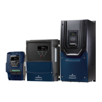
11.20 Menu 21: Second motor parameters
* The range shown for Pr 21.02 shows the range used for scaling purposes (i.e. for routing to an analog output etc.). Further range restrictions are
applied depending on the settings of Pr 1.08 and Pr 1.10.
* *These are the maximum default values. If the variable maximum of this parameter (MOTOR2_CURRENT_LIMIT_MAX) gives a lower value with
the default value of Motor rated current (Pr 21.07) the default of this parameter is at the lower value.
11.21 Menu 22: Additional Menu 0 set-up
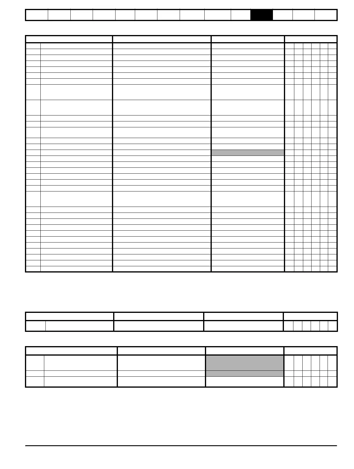
11.22 Menu 23: Header selections
Parameter Range()Default()Type
21.01
Maximum reference clamp SPEED_LIMIT_MAX rpm 1000.0 RW Uni US
21.02 Minimum reference clamp ± SPEED_LIMIT_MAX rpm* 0.0 RW Bi PT US
21.03 Reference selector 0 to 6 0 (A1.A2) RW Txt US
21.04 Acceleration rate 0 to MAX_RAMP_RATE_M2 5.000 RW Uni US
21.05 Deceleration rate 0 to MAX_RAMP_RATE_M2 5.000 RW Uni US
21.06 Base speed 0 to 10000.0 rpm 1000 RW Uni US
21.07 Rated current 0 to RATED_CURRENT_MAX A RATED_CURRENT_MAX RW Uni US
21.08 Back emf set point 0 to ARMATURE_VOLTAGE_MAX V DC
For 480V drive: 440 Eur, 500 USA
For 575V drive: 630 Eur, 630 USA
For 690V drive: 760 Eur, 760 USA
RW Uni US
21.09 Rated voltage 0 to ARMATURE_VOLTAGE_MAX V DC
For 480V drive: 440 Eur, 500 USA
For 575V drive: 630 Eur, 630 USA
For 690V drive: 760 Eur, 760 USA
RW Uni US
21.10 Armature resistance 0 to 6.0000 0.0000 RW Uni US
21.11 Motor constant 0 to 100.0% 50% RW Uni RA US
21.12
Discontinuous current controller Ki
gain
0 to 4000 200 RW Uni RA US
21.13 Continuous current controller Kp gain 0 to 4000 100 RW Uni RA US
21.14 Continuous current controller Ki gain 0 to 4000 50 RW Uni RA US
21.15 Motor 2 active OFF (0) or On (1) RO Bit NC PT
21.16 Thermal time constant 0 to 3000.0 89.0 RW Uni US
21.17 Speed controller Kp gain 0.00 to 6.5535(1 / (rad/s)) 0.0300 RW Uni US
21.18 Speed controller Ki gain 0.00 to 655.35(s / (rad/s)) 0.10 RW Uni US
21.19 Speed controller Kd gain 0.00000 to 0.65535(1/s / (rad/s)) 0.00000 RW Uni US
21.21 Speed feedback selector 0 to 5 5 RW Txt US
21.23 Rated field voltage 0 to 500 Vdc Eur: 360, USA: 300 RW Uni US
21.24 Rated field current 0 to FIELD_CURRENT_SET_MAX
Size 1: 2A Eur: 8A, USA: 8A
Size 2A&B Eur: 3A, USA: 20A
Size 2C&D Eur: 5A, USA: 20A
RW Uni NC PT US
21.25 Motor saturation breakpoint 1 0 to 100% of rated flux 50 RW Uni US
21.26 Motor saturation breakpoint 2 0 to 100% of rated flux 75 RW Uni US
21.27 Motoring current limit 0 to MOTOR2_CURRENT_LIMIT_MAX % 150.0** RW Uni RA US
21.28 Regen current limit 0 to MOTOR2_CURRENT_LIMIT_MAX % 150.0** RW Uni RA US
21.29 Symmetrical current limit 0 to MOTOR2_CURRENT_LIMIT_MAX % 150.0** RW Uni RA US
21.30 Field thermal time constant 0.0 to 3000.0 41.0 RW Uni US
21.31 Flux loop P gain 0 to 300.00 3.00 RW Uni US
21.32 Flux loop I gain 0 to 300.00 60.00 RW Uni US
21.33 Spill over P gain 0 to 300.00 0.40 RW Uni US
21.34 Spill over I gain 0 to 300.00 5.00 RW Uni US
21.35 Rated field compensation factor 0 to 100% 100% RW Uni PT US
Parameter
Range(
) Default()
Type
22.01 to
22.20
Parameter 00.xy setup Pr 0.00 to 22.99 Pr 0.00 RW Uni PT US
Parameter
Range(
) Default()
Type
23.01 Sub block headers
0 to 7 (USEr (0), SEt UP (1), diAGnoS (2),
triPS (3), SP LOOP(4), SintEr (5),
Fb SP (6), and InPut (7)
RO Uni NC PT
23.02 Or of per defined sub block enables 0 to 127 RO Uni NC PT
23.03 to
23.09
Pre defined sub block enable OFF (0) or On (1) On (1) RW Bit US
 Loading...