Safety
Information
Product
Information
Mechanical
Installation
Electrical
Installation
Getting
Started
Basic
parameters
Running the
Motor
Optimization
SMARTCARD
Operation
Onboard
PLC
Advanced
Parameters
Technical
Data
Diagnostics
UL
Information
20 Quantum MP User Guide
www.emersonct.com Issue: A4
3.5 Enclosure
3.5.1 Enclosure layout
Please observe the clearances in the diagram below taking into account any appropriate notes for other devices / auxiliary equipment when planning
the installation.
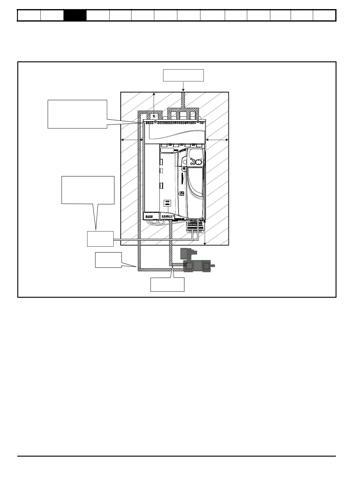
Figure 3-8 Enclosure layout Size 1
Enclosure
≥100mm
(4in)
AC supply, contactor,
line chokes
Ensure minimum clearances
are maintained for the drive.
Forced or convection air-flow
must not be restricted by any
object or cabling
Note
For EMC compliance:
1) Power cabling must be at
least 100mm (4in) from the
drive in all directions
2) Ensure direct metal contact
at drive and filter mounting
points (any paint must be
removed)
Signal cables
Plan for all signal cables
to be routed at least
300mm (12in) from the
drive and any power cable
Armature
connection
cable
Field
connection cable
≥100mm
(4in)
≥100mm
(4in)
≥100mm
(4in)
External
controller
 Loading...