Safety
Information
Product
Information
Mechanical
Installation
Electrical
Installation
Getting
Started
Basic
parameters
Running the
Motor
Optimization
SMARTCARD
Operation
Onboard
PLC
Advanced
Parameters
Technical
Data
Diagnostics
UL
Information
42 Quantum MP User Guide
www.emersonct.com Issue: A4
4.9.2 Alternative fusing
Please refer to section 12.2.1 Fuses on page 150.
Table 4-17 Quantum MP frame 1 drive SCR I
2
t rating for
semiconductor fusing
4.9.3 Internal auxiliary fuses
The internal auxiliary fuses provide protection to the field controller. The
fuses can rupture if there is a fault in the field circuit. The user should
check the internal auxiliary fuses if the drive is tripping field loss (FdL)
and the field controller is enabled.
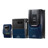
Figure 4-9 Removing the internal auxiliary fuses (size 1 shown)
Insert the screwdriver into the groove as shown above and lever
downwards to remove the fuse cover. Refer to section 4.9.1 for fuse types.
4.10 External suppressor resistor
The Quantum MP range of drives provide internal suppression of the
voltage overshoots created by commutation of the SCRs in the power
stage during the operation of the product. The internal suppression is
suitable for typical applications using recommended line reactors as
defined in section 4.4 Line reactors on page 37. The Quantum MP
drives provide the facility to allow for extra suppression for applications
at the boundaries of the drive's operating area. Applications which may
require an external suppression resistor to be installed have some or all
the following characteristics:
1. Supplies rated 10kA with less than the recommend line reactance.
2. High line-to-line voltage
The recommended external suppressor resistor selections are shown in
Table 4-18.
Table 4-18 Recommended external suppressor resistors
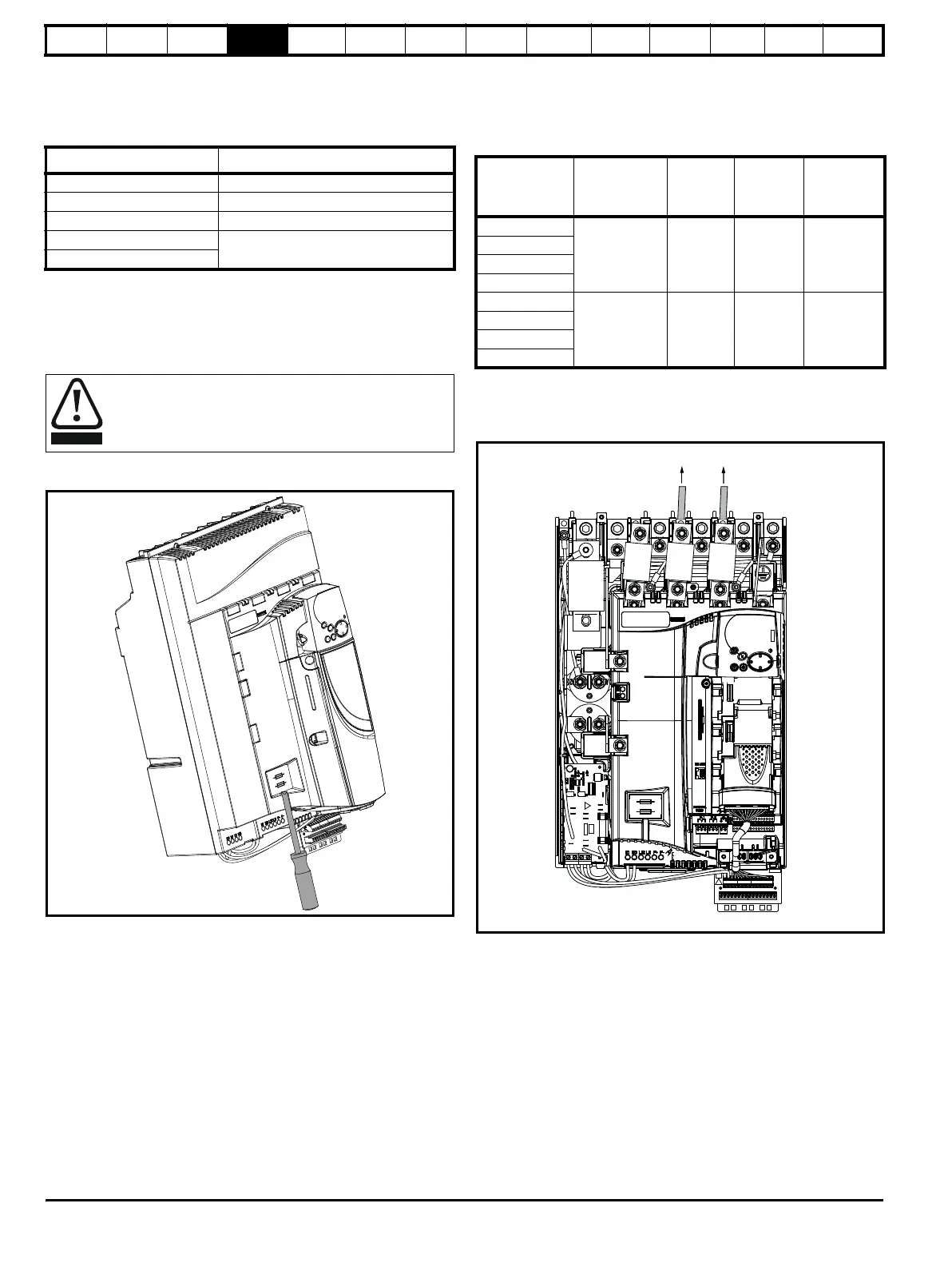
The following diagram shows the location of the external suppressor
resistor terminals above the L1 and L2 terminals:
Figure 4-10 Location of external suppressor resistor terminals,
Size 1
Model
SCR I
2
t (A
2
s)
Auxiliary 400
QMP45A4(R) 3600
QMP75A4(R) 15000
QMP155A4(R)
80000
QMP210A4(R)
Isolate the power before removing the auxiliary fuses.
Model
Resistance
Power
rating
Voltage
rating
Isolation
voltage
k
WVVrms
QMP45A4(R)
8.2 150 1100 2500
QMP75A4(R)
QMP155A4(R)
QMP210A4(R)
QMP350A4(R)
4.1 300 1100 2500
QMP400A4(R)
QMP550A4(R)
QMP700A4(R)
To external suppression resistor
 Loading...