X1 X2 Q1 Q2 Q3 Q4 Q5 Q6 Q7 Q8 Q9
Q10
Q11 Q12
1234567891011
12
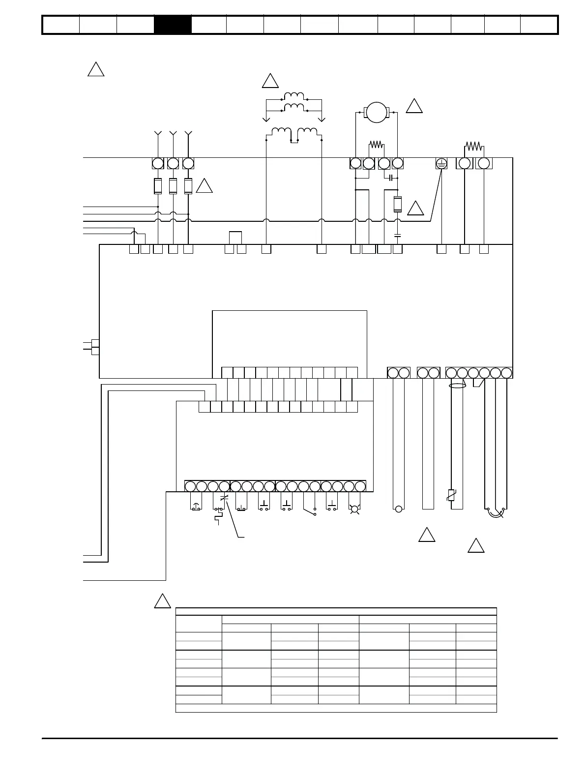
MP10 User Interface Board
SM-IO-120V Solutions Module
in Mentor MP Slot 3
N/C
N/C
E1 E3
L1 L2
F- F+ A2 MA2
L3
L12 L11 MA1
A1
PE
C1 C2 C3 C4 C5 C6 C7 C8 C9
C10
C11 C12 C13 C14 C15 C16
TB4
TB3TB2TB1
E-Stop
Stop
Interlocks
Run
Jog
Fwd
Reset
Drive
Tac h
Rev
Motor
Thermal
Enable
Speed Pot
Motor
Thermistor
(Optional)
PR
7.15
41 42 22 31 8 11 3 6 5 4
[A1] [MA1] [MA2]
[A2]
TAB 1
TAB 2
+24
Drive Enable
Analog Input 3
0 V
0 V
Analog Input 1 Inverting Input
Analog Input 1 Non-Inverting Input
+10 V, 10 mA
-
+
A2A1
DB+DB-
SR2SR1
F2
MC
- BC +
F4
F3
F2
F1
F4
F3
F1
F2
F8F6F4
L1 L2 L3
External
Suppression
Resistor
M
1
A1 [A2]
7
A2 [A1]
Motor Armature
Dynamic Brake
Resistor
Input Voltage
208/240/380/416/480 VAC
50/60 Hz
Semiconductor
(Line) Fuses
1
Mentor MP Size 1
DC
Protection
(Armature)
Fuse
Motor Field
4
300 VDC
Connection
150 VDC
Connection
CAUTION: Verify Control
Transformer is configured per
Table 1 before applying input
voltage!
3
Contactor Control 2-way plug
located near drive PE terminal
PL11 on Mentor MP90 PCB
9
5
TABLE 2 - QUANTUM MP FUSES
MODEL
LINE FUSES F4, F6, F8 - 500V
ARMATURE FUSE F2 - 700V (SEE NOTE )
CT P/N MFG P/N RATING CT P/N MFG P/N RATING
QMP45A4
3701-500090
FWH-90B 90A
3701-700090
FWP-90B 90A
QMP45A4R A50QS70-4
70A
A70QS80-4
80A
QMP75A4
3701-500125
FWH-150B 150A
3701-700125
FWP-125A 125A
QMP75A4R AQ50QS125-4
125A
A70QS125-4
125A
QMP155A4
3701-500250
FWH-250A 250A
3701-700250
FWP-250A 250A
QMP155A4R A50QS250-4
250A
A70QS250-4
250A
QMP210A4
3701-500350
FWH-350A 350A
3701-700350
FWP-350A 350A
QMP210A4R A50QS350-4
350A
A70QS350-4
350A
NOTE: ARMATURE FUSE IS ONLY USED ON "R" MODEL FOUR QUADRANT DRIVES
1
on MP14
PCB
on MP14
PCB
ON
 Loading...