Safety
Information
Product
Information
Mechanical
Installation
Electrical
Installation
Getting
Started
Basic
parameters
Running the
Motor
Optimization
SMARTCARD
Operation
Onboard
PLC
Advanced
Parameters
Technical
Data
Diagnostics
UL
Information
28 Quantum MP User Guide
www.emersonct.com Issue: A4
4.1 Electrical connections/ Power connections
4.1.1 AC and DC connections
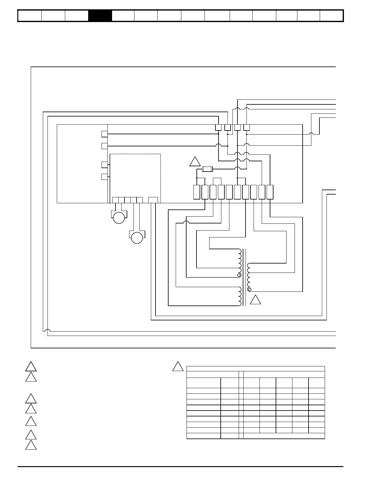
To understand the function of the different power connections, refer to Figure 4-1 and Figure 4-2 for size 1 drives and Figure 4-3 and Figure 4-4 for
the size 2 drives.
Figure 4-1 Power connections for 480V drive, Quantum MP size 1
X1 X2 E1 E3
A B C D E F G H I J
F3
+
-
+
-
PL1
BC
RED
BLACK
BLACK
GRAY
ORANGE
RED
PURPLE
BLUE
WHITE
YELLOW
1
2
3
4
5
7
8
9
Contactor Control Signal
MC
RED
BLACK
Brake
Contactor
Motor
Contactor
Contactor Control
Circuitry
MP18MP19
Contactor Power
Supply
30 V
120 V
2
Quantum MP Size 1
3
480 VAC connections
shown. Configure per
Table 1.
TABLE 1 - T1 TRANSFORMER CONNECTIONS BY SUPPLY VOLTAGE
TRANSFORMER SUPPLY VOLTAGE - L1/L3 50/60 Hz
LEAD COLOR
PIN
208V 240V 380V 416V 480V
RED
1
BBBBB
YELLOW
2
FFDDD
ORANGE
3
AAE
CC
GRAY
4EE
C
EE
BLACK
5
GGGGG
WHITE 7 J J J J J
BLUE
8
HIHHI
PURPLE
9
IHI IH
TERMINAL
3
1
NOTES:
See Table 2 for values.
Quantum MP control power fuse F3 - All Models:
CT P/N = 212011-05
Cooper-Bussmann P/N FNQ-R-1/2
Ferraz-Shawmut P/N ATQR1/2
See Table 1 for proper connection.
Motor Field - 8A max. Connection shown is for 300 VDC Field. For 150 VDC -
Remove jumper from F2 to F3 and connect F1 to F3 and F2 to F4
Enable Input must be pulled high (+24V) as shown for drive to enter Ready "rdy"
state. Otherwise, drive display will show "inh" (Inhibited).
Designators in brackets [ ] refer to regenerative models only (QMPXXXA4R).
Optional motor thermistor input if not used set parameter 7.15 = 6 (Volt). When
fault occurs, drive display will show the fault.
2
1
3
4
5
7
9
CON 1
 Loading...