Safety
Information
Product
Information
Mechanical
Installation
Electrical
Installation
Getting
Started
Basic
parameters
Running the
Motor
Optimization
SMARTCARD
Operation
Onboard
PLC
Advanced
Parameters
Technical
Data
Diagnostics
UL
Information
32 Quantum MP User Guide
www.emersonct.com Issue: A4
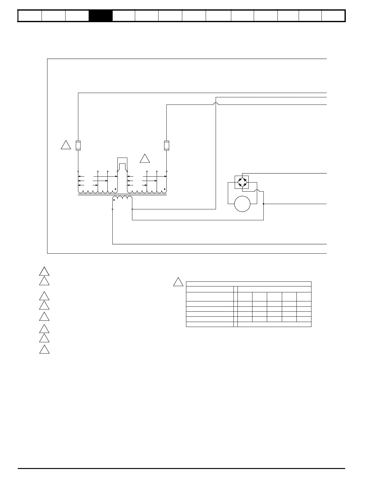
Figure 4-3 Power connections for Quantum MP size 2 drives
Quantum MP Size 2
3
1
NOTES:
See Table 2 for values.
Quantum MP control power fuses
F3A, F3B - Ferraz ATQR1
Bussmann FRQR1
See Table 1 for proper connection.
Motor Field - 20A max. Connection shown is for 300 VDC Field. For 150 VDC -
Remove jumper from F2 to F3 and connect F1 to F3 and F2 to F4
Enable Input must be pulled high (+24V) as shown for drive to enter Ready "rdy"
state. Otherwise, drive display will show "inh" (Inhibited).
Designators in brackets [ ] refer to regenerative models only (QMPXXXA4R).
Optional motor thermistor input if not used set parameter 7.15 = 6 (Volt). When
fault occurs, drive display will show the fault.
N.C. MC contact (Dynamic Braking) is only supplied on Models QMP350A4
and QMP400A4.
1
2
9
7
5
4
3
F3A
TABLE 1 - T1 TRANSFORMER CONNECTIONS BY SUPPLY VOLTAGE
TRANSFORMER SUPPLY VOLTAGE - L1/L3 50/60 Hz
LEAD
208V 240V 380V 416V 480V
E1F H2 H1 H3 H2 H1
E3F H8H8H8H8H8
JUMPER A
H4-H8 H4-H8
H4-H7
H4-H6
H4-H5
JUMPER B H2-H6 H1-H5 H4-H7 H4-H6 H4-H5
TERMINAL
MC
115V
X1
X2
H4 H3 H2 H1H5H6H7H8
T1
A
B
F3B
190V
208V
230V
190V
208V
230V
E3F
E1F
E3
E1
3
10
2
BR1
 Loading...