Safety
Information
Product
Information
Mechanical
Installation
Electrical
Installation
Getting
Started
Basic
parameters
Running the
Motor
Optimization
SMARTCARD
Operation
Onboard
PLC
Advanced
Parameters
Technical
Data
Diagnostics
UL
Information
Quantum MP User Guide 69
Issue: A4 www.emersonct.com
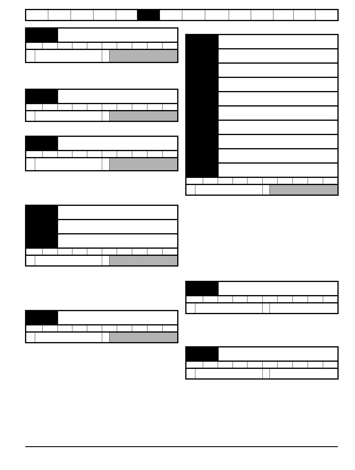
The current feedback signal is derived from internal current
transformers. It is used for closed loop control and indication of the
armature current, and to initiate motor protection.
Indicates the field current feedback in 0.01 amperes.
The average measured DC output voltage seen across the drive A1 and
A2 terminals or the average measured DC output voltage seen across
the motor. Selected by Pr 5.14.
The armature voltage feedback has a resolution of 10-bit plus sign.
These parameters are controlled by the drive sequencer as defined in
Menu 6. They select the appropriate reference as commanded by the
drive logic. di11 (Pr 0.46, 1.11) will be active if a run command is given,
the drive is enabled and the drive is ok. This parameter can be used as
an interlock in a Onboard PLC or SM-Applications program to show that
the drive is able to respond to a speed or torque demand.
The parameter displays the software version of the drive.
6.1.4 Trips
Contains the last 10 drive trips. tr01 (Pr 0.51, 10.20) is the most recent
trip and tr10 (Pr 0.60, 10.29) the oldest. When a new trip occurs all the
parameters move down one, the current trip is put in tr01 (Pr 0.51,
10.20) and the oldest trip is lost from the bottom of the log. Descriptions
of the trips are given in Table 13-1 on page 157. All trips are stored,
including HF trips numbered from 20 to 29. (HF trips with numbers from
1 to 16 are not stored in the trip log.) Any trip can be initiated by the
actions described or by writing the relevant trip number to Pr 10.38. If
any trips shown as user trips are initiated the trip string is "txxx", where
xxx is the trip number.
6.1.5 Speed loop
SP01 (Pr 0.61/3.10) operates in the feed-forward path of the speed-
control loop in the drive. See Figure 11-3 on page 104 for a schematic of
the speed controller. For information on setting up the speed controller
gains, refer to Chapter 8 Optimization on page 78.
SP02 (Pr 0.62, 3.11) operates in the feed-forward path of the speed-
control loop in the drive. See Figure 11-3 on page 104 for a schematic of
the speed controller. For information on setting up the speed controller
gains, refer to Chapter 8 Optimization on page 78.
di08
{0.43, 4.01}
Current magnitude
RO Uni FI NC PT
0 to DRIVE_CURRENT_MAX
A
di09
{0.44, 5.56}
Field current feedback
RO Bi FI NC PT
±50.00A
di10
{0.45, 5.02}
Armature voltage
RO Bi FI NC PT
±ARMATURE_VOLTAGE_
MAX V
di11
{0.46, 1.11}
Reference enabled indicator
di12
{0.47, 1.13}
Reverse selected indicator
di13
{0.48, 1.14}
Jog selected indicator
RO Bit NC PT
OFF (0) or On (1)
di14
{0.49, 11.29}
Software version
RO Uni NC PT
1.00 to 99.99
tr01
{0.51, 10.20}
Trip 0
tr02
{0.52, 10.21}
Trip 1
tr03
{0.53, 10.22}
Trip 2
tr04
{0.54, 10.23}
Trip 3
tr05
{0.55, 10.24}
Trip 4
tr06
{0.56, 10.25}
Trip 5
tr07
{0.57, 10.26}
Trip 6
tr08
{0.58, 10.27}
Trip 7
tr09
{0.59, 10.28}
Trip 8
tr10
{0.60, 10.29}
Trip 9
RO Txt NC PT PS
0 to 229
SP01
{0.61, 3.10}
(Kp1) Speed controller proportional gains
RW Uni US
0.0000 to 6.5535 (1 / (rad/s))
0.0300
SP02
{0.62, 3.11}
(Ki1) Speed controller integral gains
RW Uni US
0.00 to 655.35 (s / (rad/s))
0.1
 Loading...