Safety
Information
Product
Information
Mechanical
Installation
Electrical
Installation
Getting
Started
Basic
parameters
Running the
Motor
Optimization
SMARTCARD
Operation
Onboard
PLC
Advanced
Parameters
Technical
Data
Diagnostics
UL
Information
36 Quantum MP User Guide
www.emersonct.com Issue: A4
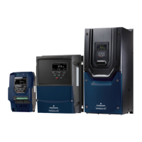
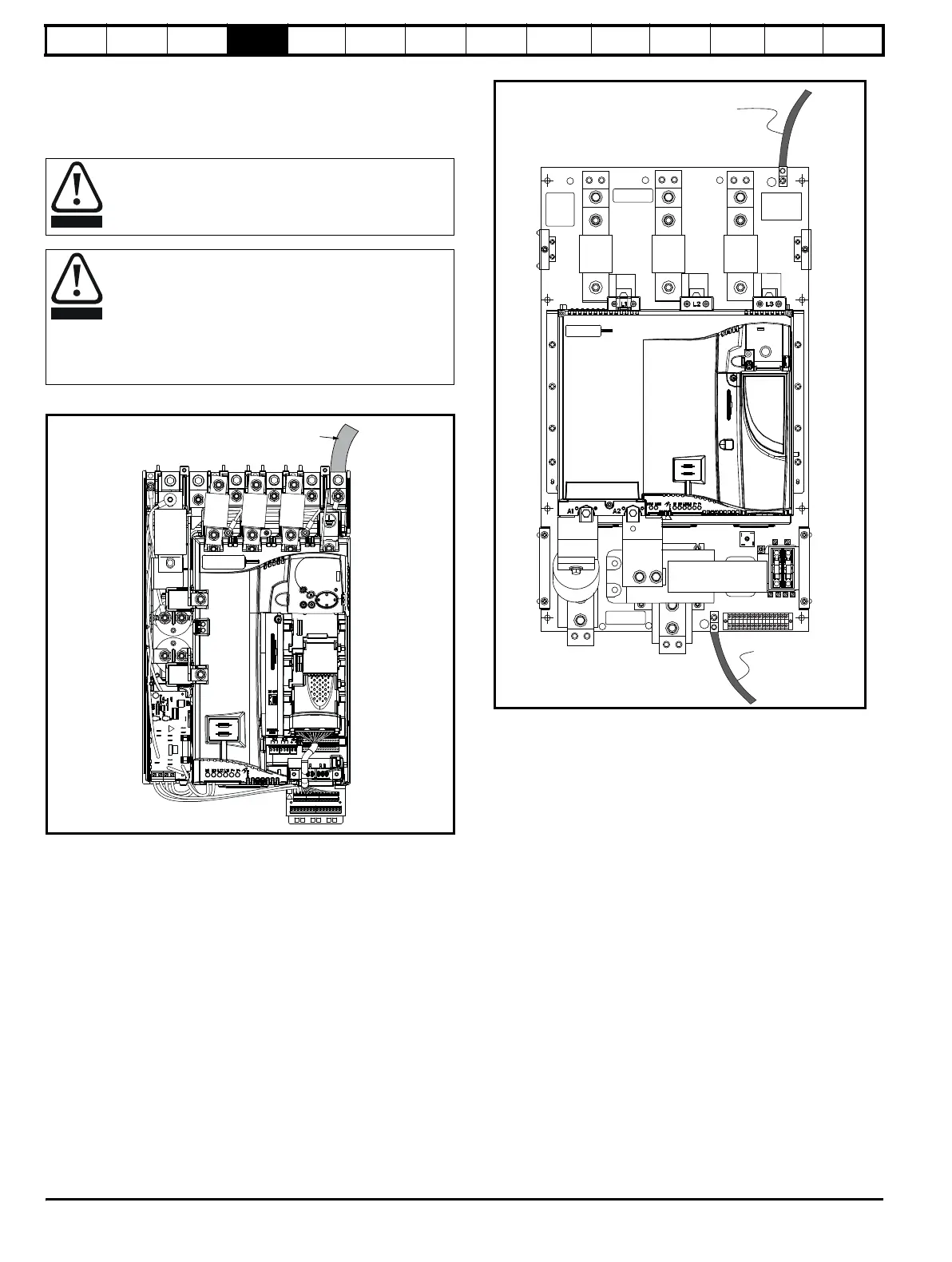
4.2 Ground connections
The drive must be connected to the system ground of the AC supply.
The ground wiring must conform to local regulations and codes of
practice.
Figure 4-5 Location of ground connection, Size 1
Figure 4-6 Location of ground connection, Size 2
4.3 AC supply requirements
The standard drive is rated for a nominal supply voltage up to 480 Vrms.
4.3.1 Supply types
Drives are suitable for use with any supply type, i.e. TN-S, TN-C-S, TT,
IT, with grounding at any potential, i.e. neutral, centre or corner
(“grounded-delta”).
4.3.2 MOV ground disconnect
The facility for disconnecting the link between varistors and ground is
provided for special circumstances, where a sustained high voltage may
be present between lines and ground, for example during a high
potential test or in certain situations with IT supplies and multiple
generators. If the link is disconnected then the immunity of the drive to
high voltage impulses is reduced. It is then only suitable for use with
supplies having overvoltage category II, i.e. not for connection at the
origin of the low voltage supply within a building.
Where there is a possibility of temporary condensation or
corrosion occurring, the ground connection should be
protected from corrosion by suitable jointing compound.
Ground loop impedance
The ground loop impedance must conform to the
requirements of local safety regulations.
The drive must be grounded by a connection capable of
carrying the prospective fault current until the protective
device (fuse, etc,) disconnects the AC supply.
The ground connections must be inspected and tested at
appropriate intervals.
Ground
Connection
DANGER
HIGH VOLTAGE
DANGER
HIGH VOLTAGE
Ground
Connection
Ground
Connection
L1
L2 L3
A+
A-
GND
GND
 Loading...