3. Install CTs for Metering
The IQ Envoy uses terminal blocks for metering connections. The UL listed energy-monitoring CTs provide
revenue-grade production metering and provide (optional) consumption metering. When wiring the IQ Envoy
for production and consumption metering, be sure to install the current transformers (CTs) exactly as
described for your application. You must use a protected route in conduit for the CT wires from the AC mains
to the IQ Envoy. If you need to extend the leads, see “Extend Consumption CT Leads, If Needed” on page 16.
DANGER! Do not install CTs when current is flowing in the sensed circuit. Always install CT wires in the
terminal blocks before energizing the sensed circuit.
DANGER! Risk of electric shock. Be aware that installation of this equipment includes risk of electric shock.
If you wire the IQ Envoy at the subpanel, always de-energize the main load center before beginning wiring. If
the subpanel cannot be de-energized, a qualified electrician may safely install the CTs as directed, making
sure to connect the leads and then place the CTs around each wire and latch.
WARNING! Do not install the CTs in a panel where they exceed 75% of the wiring space of any cross-
sectional area within the panel.
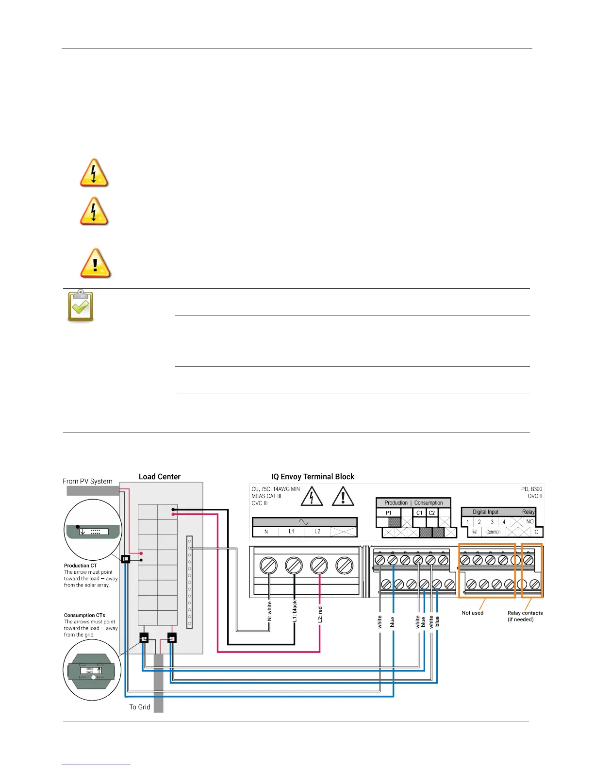
When wiring the IQ Envoy for production and consumption metering, be sure to install the
current transformers (CTs) exactly as described for your application.
When installing CTs, it is important to match CT and sense voltage phases. Be sure to
consistently identify the two AC lines at three points: the main load center feed, the
Envoy, and the solar production circuit breaker. Wire colors (typically black and red) may
Do not install the CTs in a panel where they exceed 75% of the wiring space of any cross-
sectional area within the panel, or refer to local standards for guidance.
Only run active conductors through the CT. The CT can monitor multiple active
conductors. You may run more than one wire through the CT if all wires are on the same
phase and they fit the opening in the CT.
 Loading...


