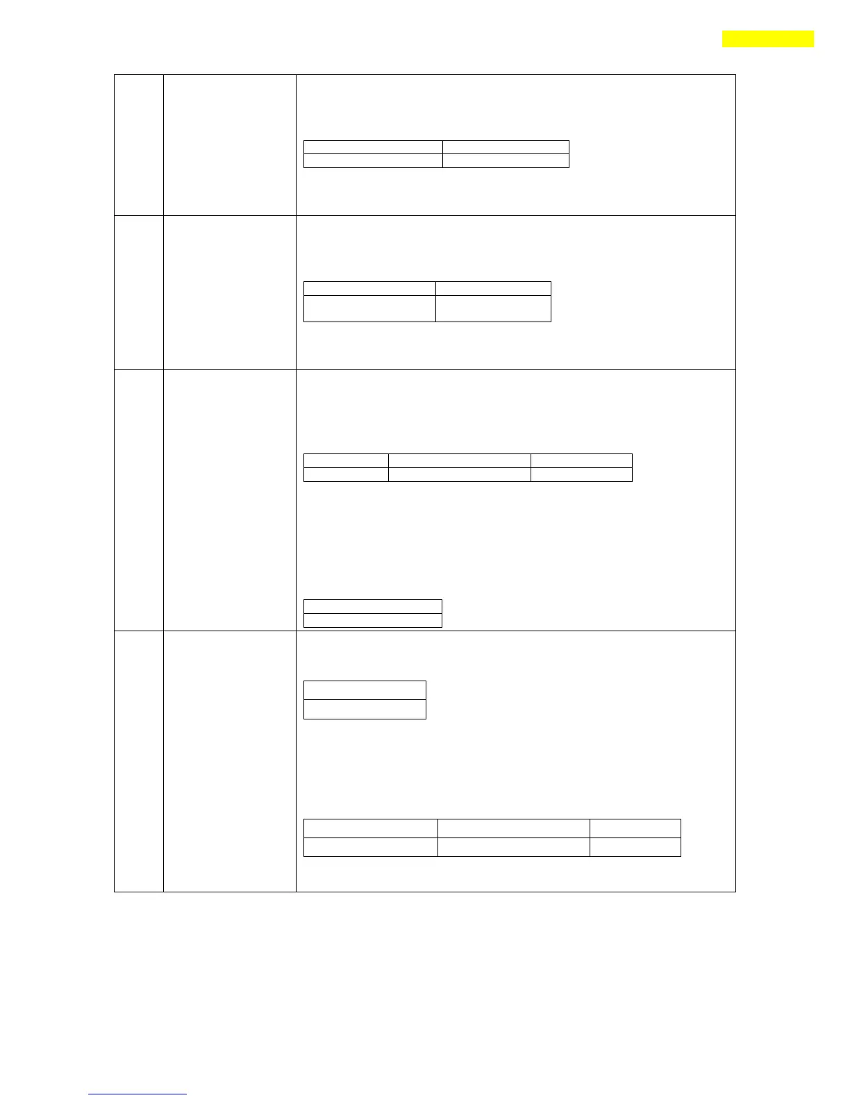
Current input signal status of the control input port is recognized.
Sending : 0 byte
Response : 5 byte
Relevant bit by each input signal, refe r to 「1-2-4. Bit setup of Input Pin」.
Current output signal status of the control output port is recognized.
Sending : 0 byte
Response : 5 byte
Relevant bit by each output signal, refer to 「1-2-3.Bit setup of Output
Pin」.
Assign I/O signal to the pin of CN1 port and set signal level
simultaneously. By running ‘FAS_SaveAllParameters’, you can save the
setting value to the ROM.
Sending : 6 bytes
♦ I/O number: ‘0~11’ corresponds to ‘Limit+, Limit-, Org,IN1,…,
IN9’ respectively, and ‘12~22’ corresponds to ‘COMP, OUT1,…,
OUT9’ respectively.
♦ I/O pin masking data: Refer to 「1-2-4. Bit setup of Input Pin」.
♦ Level Setting: 0:Active Low, 1:Active High
Response : 1 byte
Recognize pin setting status of CN1 port from RAM .
Sending : 1 byte
♦ I/O number: ‘0~11’ corresponds to ‘Limit+, Limit-, Org, IN1, …,
IN9’ respectively, and ‘12~22’ corresponds to ‘COMP, OUT1, …,
OUT9’ respectively.
Response : 6 bytes
For more information, refer to ‘0x24’Frame type.
 Loading...