Do you have a question about the FlexRadio Systems FLEX-5000 Series and is the answer not in the manual?
| Brand | FlexRadio Systems |
|---|---|
| Model | FLEX-5000 Series |
| Category | Transceiver |
| Language | English |
Details unpacking and initial placement considerations for the FLEX-5000.
Factors to consider when choosing a location for the FLEX-5000 in your shack.
Explains how to connect the radio's front and back panel ports.
Details the connectors and controls on the front panel of the FLEX-5000.
Details various back panel ports including antenna, power, FireWire, and audio connections.
Instructions for connecting peripherals to the FLEX-5000C's embedded computer.
Guidance on connecting the FLEX-5000C to a local area network or modem.
Step-by-step instructions for installing the FLEX-5000C.
Steps to set up and configure the pre-installed operating system.
Step-by-step instructions for installing the FLEX-5000A.
Configures driver settings like sample rate, buffer size, and operation mode.
Guidance on upgrading from a previous version of PowerSDR.
Steps for downloading and installing the PowerSDR software.
Outlines the steps for the initial PowerSDR setup wizard.
Parameters and settings for the initial configuration of PowerSDR.
Configures audio settings like buffer size, sample rate, and latency.
Configures antenna ports and external keying lines for each band.
Controls the audio lines into and out of the FLEX-5000, similar to Windows sound mixer.
The main tuning VFO for the primary receiver RX1 and the transmitter.
Details controls for synchronizing VFOs, locking frequency, and adjusting tune steps.
The secondary VFO, used in specific instances and for tuning RX2.
Explains the RX1, RX2, and TX meters for monitoring signal parameters.
Controls for selecting operating bands and saving/recalling band settings.
Options for changing the demodulation routine and selecting modes like LSB, USB, CW, etc.
Settings for customizable, mode-specific filters and variable filter adjustments.
Adjusts settings specific to the selected transmission mode (Phone, CW, Digital).
Controls for adjusting display views like Panadapter, Waterfall, and Spectrum.
Enables a second receive channel within the passband for RX1.
Configures DSP functions like noise reduction, blankers, and filters.
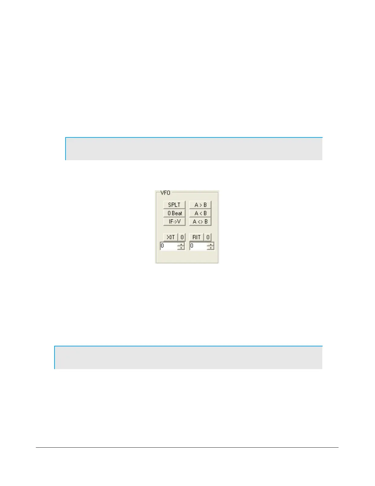
Controls for manipulating VFO frequencies and settings like Split, RIT, and XIT.
Displays total CPU load, indicating potential performance issues.
Activates/deactivates PowerSDR and acts as an RX/TX indicator.
Monitors transmitted audio through receiver speakers for adjustments.
Resets the radio's options and current state to default.
Imports settings from a backwards-compatible database file.
Configures general settings including hardware, options, calibration, and RX2.
Configures audio settings including buffer size, sample rate, and VAC.
Customizes the appearance of spectrum, waterfall, and meter displays.
Configures DSP functions like noise reduction, blankers, and filters.
Adjusts phase and gain for receive and transmit image rejection.
Configures CW keyer settings including pitch, connections, and options.
Customizes AGC, Leveler, and ALC settings for user preference.
Tailors transmit signal characteristics using compression and filtering.
Configures power amplifier settings, including gain by band.
Customizes the appearance of the front console elements.
Associates keyboard keys with operating functions as shortcuts.
Enables interface with third-party logging and remote control software.
Provides tools for testing transmitter IMD, audio balance, and signal generation.
Allows saving and retrieving frequency, mode, filter, and other settings.
Enables recording and playback of station audio or pre-processed IF audio.
Provides 3-band, 10-band, or 100-band equalizers for audio modification.
Configures up to 16 external transverters for use with PowerSDR software.
Controls automatic Morse code transmission and sending code from the keyboard.
Controls audio lines into and out of the FLEX-5000, similar to Windows sound mixer.
Configures antenna ports and keying lines for receivers and transmitter.
Controls the internal, optional Antenna Tuning Unit (ATU).
Step-by-step instructions for powering up the FLEX-5000 transceiver.
Step-by-step instructions for powering down the FLEX-5000 transceiver.
Explains various methods for tuning signals using the radio interface.
Setup procedure for quickly establishing voice transmission (SSB, AM, or FMN).
Setup procedure for quick CW transmissions using internal/external keyers.
Guides operation with third-party programs using CAT and virtual COM ports.
Connects PowerSDR to digital mode programs via CAT and Audio connections.
Sets up PowerSDR to connect to third-party software via CAT control.
Sets up PowerSDR to connect to third-party CW programs using CAT port.
Utilizes virtual sound connections for digital mode programs.
Enables PowerSDR for programs using the default sound device.
Details the technical specifications for the FLEX-5000A and FLEX-5000C transceivers.
Details specifications for the FLEX-5000C's embedded computer hardware and software.
Shows the full duplex/triplex architecture of the FLEX-5000 transceiver.
FCC and EU compliance statements for the FLEX-5000A transceiver.
Illustrates how buffer size and sample rate affect filter bandwidth, slope, and latency.
Explains how buffer size and sample rate affect system latency.
Explains fundamental theory behind signal processing, DFT, and FFT.
How to update firmware using the FlexLoader utility automatically.
Steps for manually updating the FLEX-5000 firmware.
Instructions for downloading and extracting firmware files.
Procedure to execute the firmware update using the Burn.bat file.
Shows input/output signal levels at different Max Gain settings with Slope set to zero.
Describes the rectangular window function with no shaping applied.
Explains Hanning and Hamming windows based on raised cosine shape.
Discusses Blackman window functions used for signal processing chain filters.
Mentions less common window functions for completeness and experimentation.