Page 37
Fresenius 2008
®
K Calibration Procedures
P/N 507296 Rev D
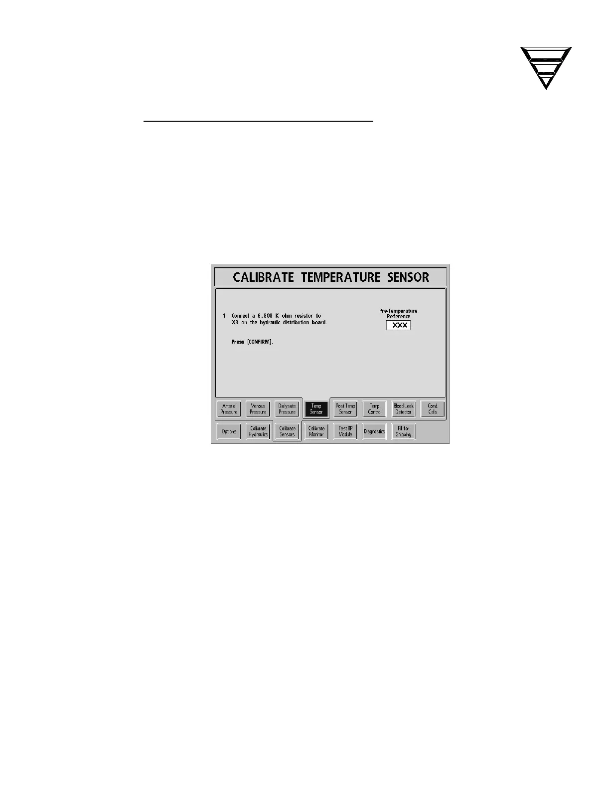
2.3.4 TEMPERATURE SENSOR CALIBRATION
Perform the temperature sensor calibration as follows using the test connector set
referenced in Section 1.1. The display screen calls for connecting specific
resistances to the X3 (MON-NTC) connector position on the distribution panel
(See Figure 1, pg. 5) for each test. The test connectors contain resistors which are
the closest 1% tolerance resistor available to these values. In the following
procedure, each test connector is identified by the number marked on its cover.
From the Calibrate Sensors screen, select the Temp Sensor screen button.
The screen will change to the following:
1. Remove the distribution board cover from the back of the machine.
Unplug the X3 (MON-NTC) connector from the distribution board.
Connect test connector 34 (6.808K) into X3 (MON-NTC) connection on
the distribution board.
Press the [CONFIRM] key to save the data. The screen will change.
2. Remove the previous test connector and connect test connector 41
(5.117K) into X3 (MON-NTC) connection on the distribution board.
Press the [CONFIRM] key to save the data. The screen will change.

 Loading...