Discharge Temp. Sensor 1 Error
OK
OK
DC
Discharge temp. sensor 1
Discharge temp. sensor 1 short detected
Discharge temp. sensor 1 open detected after compressor 1 operated
continuously for 5 minutes or more
1. Connector connection defective, open
2. Sensor defective
3. Main PCB defective
Check Point 1 : Check the connector connection and cable open
Connector connection state check
Cable open check
Check Point 2 : Check the sensor
Sensor characteristics check (Disconnect the sensor from the PCB and check.)
* For the sensor characteristics, refer to the "Service Parts Information 25".
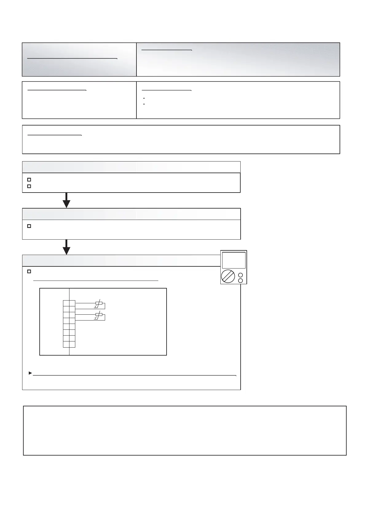
Check Point 3 : Check voltage of Main PCB (DC5.0V)
Main PCB (CN162: 1-2) voltage value = 5V
Remove the sensor from Main PCB, check the voltage.
If the voltage does not appear, replace Main PCB and set up original address.
Discharge temp. sensor 1 (CN162: 1-2)
Indoor Unit : Operation LED 9 times Flash, Timer LED 15 Times Flash,
Filter LED Continuous Flash.
Outdoor Unit : E. 7 1. 1
Error Code : 9 U / 7 1
Trouble shooting 35 E71. 1
Indicate or Display:
Detective Actuators:
Detective details:
OUTDOOR UNIT Error Method:
Forecast of Cause :
1
2
3
4
5
6
7
8
BLACK
BLACK
BLACK
BLACK
THERMISTOR (DIS.TEMP.1)
THERMISTOR (COMP SHELL 1)
CN162
Caution
By changing of DIP SW 4-2 to ON, the Back-up operation can start when the active outdoor unit exists on the multi outdoor unit connection.
(Stand alone outdoor unit is impossible)
The following conditions will be concerned in use of back-up operation. (Please do not use the system with back-up operation for long time.)
- The operating compressor life time becomes shorter.
- The operating performance may drop due to the limited active compressor(s).
- The compressor may stop frequently by protection controlling.
*In order to keep the operating capacity, the release of the Low noise mode setting might be necessary.
1
2
3
4
5
6
7
8
04-44
 Loading...