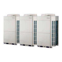
Remove the connectors.
Remove the 2 mounting screws
and the spacers.
Note the tightening torque at the installation.
Tightening torque is as follows.
- Temporary tightening : 0.3 +0.1N m
- Final tightening : 1.3 +0.1N m
8. Fan driver PCB removal
06-06
Fan driver PCB
Screws
(For IPM)
Spacers Spacers
-
-
.
.
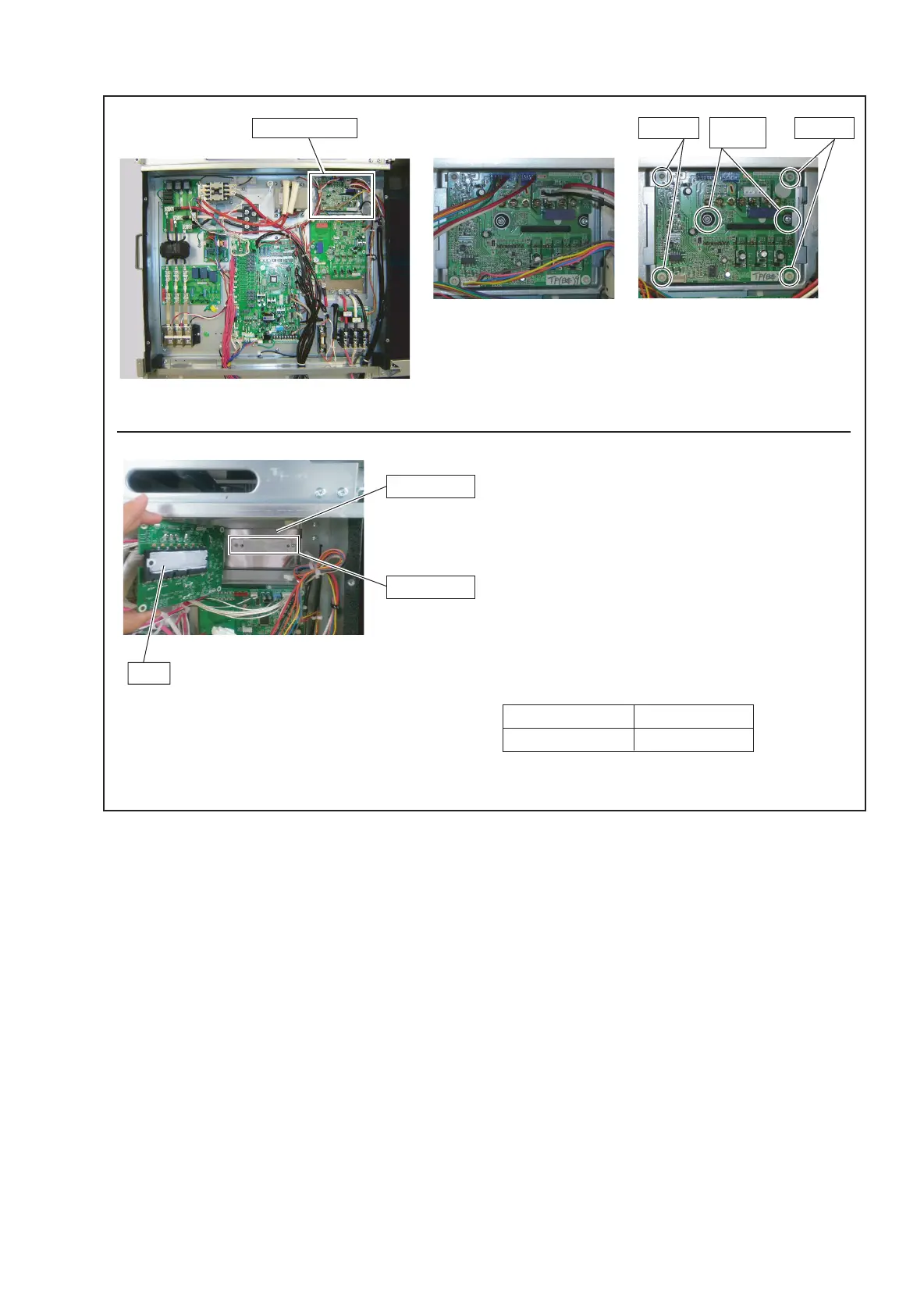
IPM
Heat sink L
Heat sink K
- Spread the heat dissipation compound on the other side of IPM
when you exchange Fan driver PCB by the repair.
- Spread the heat dissipation compound without a gap between
the Heat sink L and Heat sink K.
HEAT SINKER(20g) 0000036795
Service Parts No.
Parts Name
Compound
 Loading...