1. OPERATIONAL OVERVIEW
1-71
1.48 How to Change the Reference Position
The reference position for measurements (range, bearing, etc.) and markers (heading
line, stern mark, etc.) can be the radar antenna position ([ANT]) or the consistent com-
mon reference point ([CCRP]).
The reference position is a location on own ship to which all horizontal measurements,
for example range, bearing, relative course, relative speed, closest point of approach
(CPA) or time to closest point of approach (TCPA), are normally referenced.
[CCRP] for this series of radars is fixed at the conning position and [ANT] is fixed at
the radar antenna position.
To change the reference position, use the Touchpad to place the cursor over the "REF
POINT" indication at the top of the screen, then press the left button to select [ANT]
or [CCRP] as applicable. You can also change the reference by rotating the ADJUST
knob when the cursor is placed over the indication.
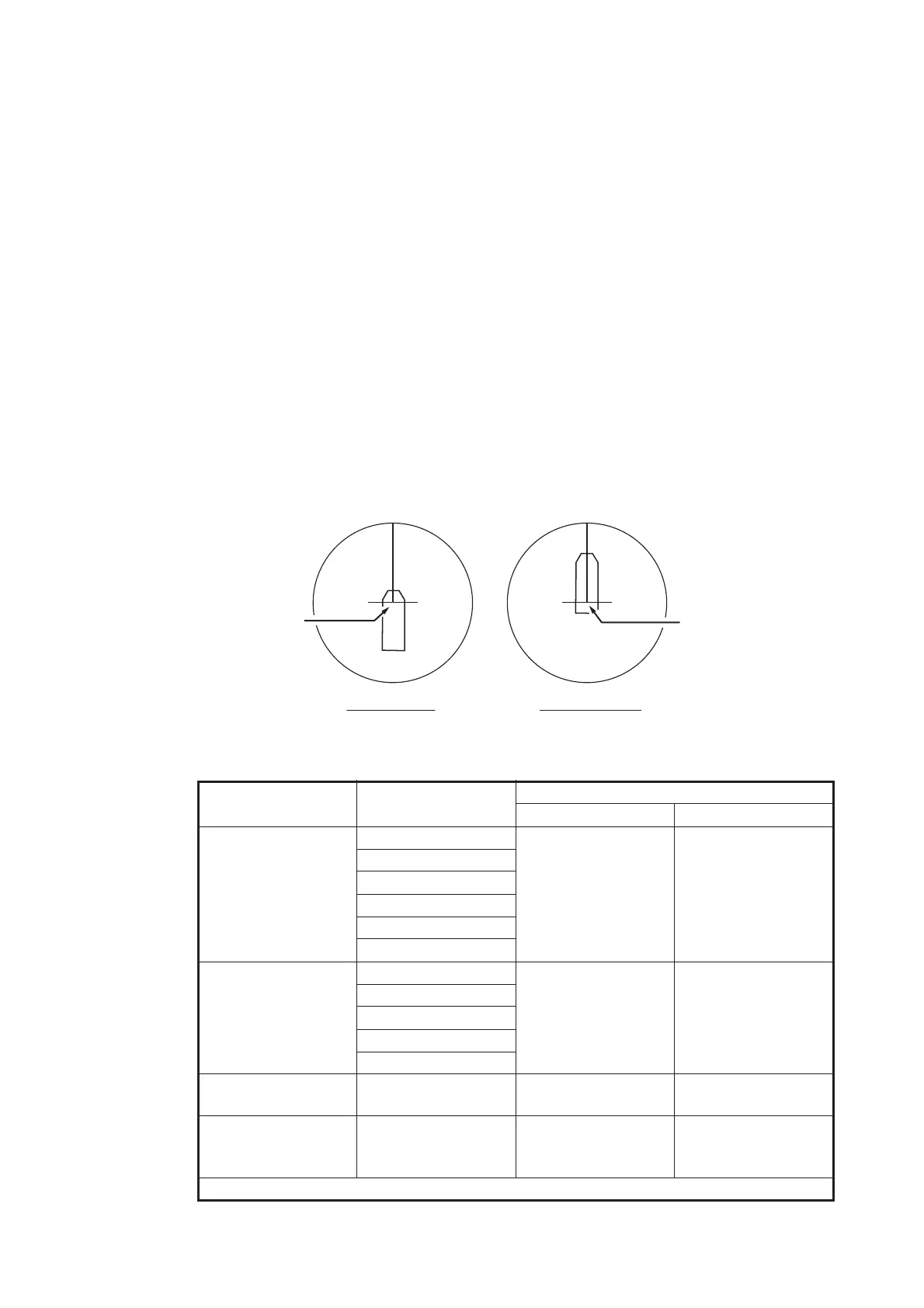
The position of the own ship marker changes according to reference position as
shown below. If the CCRP is positioned outside of the effective display area, the bear-
ing scale is indicated with the appropriate reduced detail.
Range and bearing are measured and graphics are drawn according to reference po-
sition as in the table below.
Category Item
Reference point
ANT CCRP
Range and bearing
measurements
EBL Range and bearing
measured from an-
tenna position.
Range and bearing
measured from
CCRP.
VRM
Cursor
PI line
Range ring
Drop mark
Graphics Heading line Drawn from anten-
na position.
Drawn from CCRP.
Stern mark
Beam line
Own ship vector
Own ship track
Bearing cursor Drawn with antenna
position at center.
Drawn with CCRP
at center.
Course, speed Calculated with an-
tenna position at
center.
Calculated with
CCRP at center.
Continued on next page
X
CCRP position
X
ANT position
Radar antenna
position is at
center of display
Conning position is at
center of display
 Loading...