38
Servo reversing (
REVERSE
): changes the direction an individual servo responds to a CONTROL STICK motion.
[Since channel 9 and 10 are switch only, its servo
REVERSE
is in the
AUX-CH
control screen with its switch assignment. See p. 46.]
For CCPM helicopters, be sure to read the section on
SWASH AFR
(p. 95) before reversing any servos.
With the exception of CCPM helicopters, always complete your servo reversing prior to any other programming.
When using
ACRO
GLID
functions that control multiple servos, such as
FLAPERON
or
V-TAIL
, it may be confusing to determine whether the servo needs
to be reversed or a setting in the function needs to be reversed. Refer to the
instructions for each specialized function for further details.
Always check servo direction prior to every flight as an additional
SUHFDXWLRQWRFRQ¿UPSURSHUPRGHOPHPRU\KRRNXSVDQGUDGLRIXQFWLRQ
NOTE:
THR-REV
is a special function that reverses the entire throttle control, including moving the trim functionality to
the Stick’s upper half. To use
THR-REV
, turn off the transmitter, hold down the MODE and END keys, turn on. CURSOR
DOWN to
THR-REV
and turn the DIAL to
REV
. Turn the transmitter off and back on. This change affects all models in the
radio. (
GLID
only): The separate
THR-REV
settings for each model can be set, see p.36.
GOAL of EXAMPLE: STEPS: INPUTS:
Reverse the direction of the elevator
servo.
Open
REVERSE
function.
for 1 second.
(If
ADVANCE
, again.)
to
REVERSE
.
Choose proper channel and set
direction. (Ex:
ELEV REV
)
to
ELEV
.
to
REV
. for 1 second.
Close.
Where next? Adjust servo travel with
END POINT
: see p. 39.
6HWXSGXDOWULSOHUDWHVDQGH[SRQHQWLDO
D/R
,
EXP
): see p. 42.
6HWXSÀLJKWWLPHUVVHHS
Set up trainer functions: see p. 47.
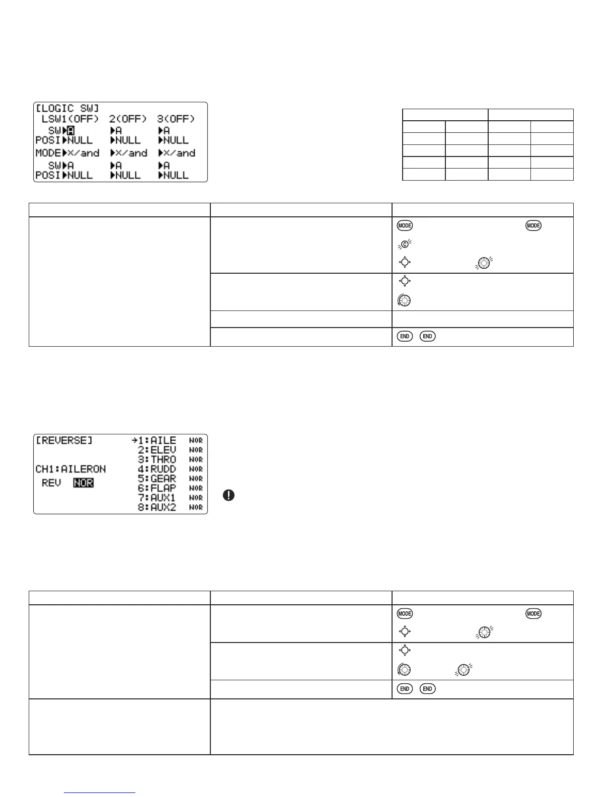
Logic switch selection (
LOGIC SW
): The various functions in the T10CG can be selected by switch. The Logic switch can
be assigned to the following functions:
THR-CUT
,
IDLE DOWN
,
AUX-CH
,
TIMER
,
PROG. MIX
,
AIRBRAKE
,
ELEV-FLAP
, and
AILE-
FLAP
functions. The logic switch can activate functions by two switches combinations. It is also possible to select from 2
types of logic, either AND or OR, can be selected.
Adjustability:
• Three logic switches can be used.
(Lsw1, Lsw2, and Lsw3)
• SW(1), SW(2), SW(3):
Any
SWITCH A-H or THR-STKS
• Switch position (
POSI
)
• Logic mode: AND or OR (
MODE
)
Logic combination table:
SWITCH LOGIC
SW(1) SW(2) AND OR
off off off off
off on off on
on off off on
on on on on
GOAL of EXAMPLE: STEPS: INPUTS:
Ex: Switch A and B are calculated by
AND logic. (A = down, B = down)
Open BASIC menu, then open
LOGIC
SW
menu.
for 1 second.
(If
ADVANCE
, again.)
to 2nd page of menu.
to
LOGIC SW
.
Go to
POSI
and change setting.
(Ex:
DOWN
)
to
POSI
.
to
DOWN
.
Next,
SW
=
B
,
POSI
=
DOWN
Repeat.
Close.