1-4 COBE 2991 Cell Processor • Essentials Guide
Introduction
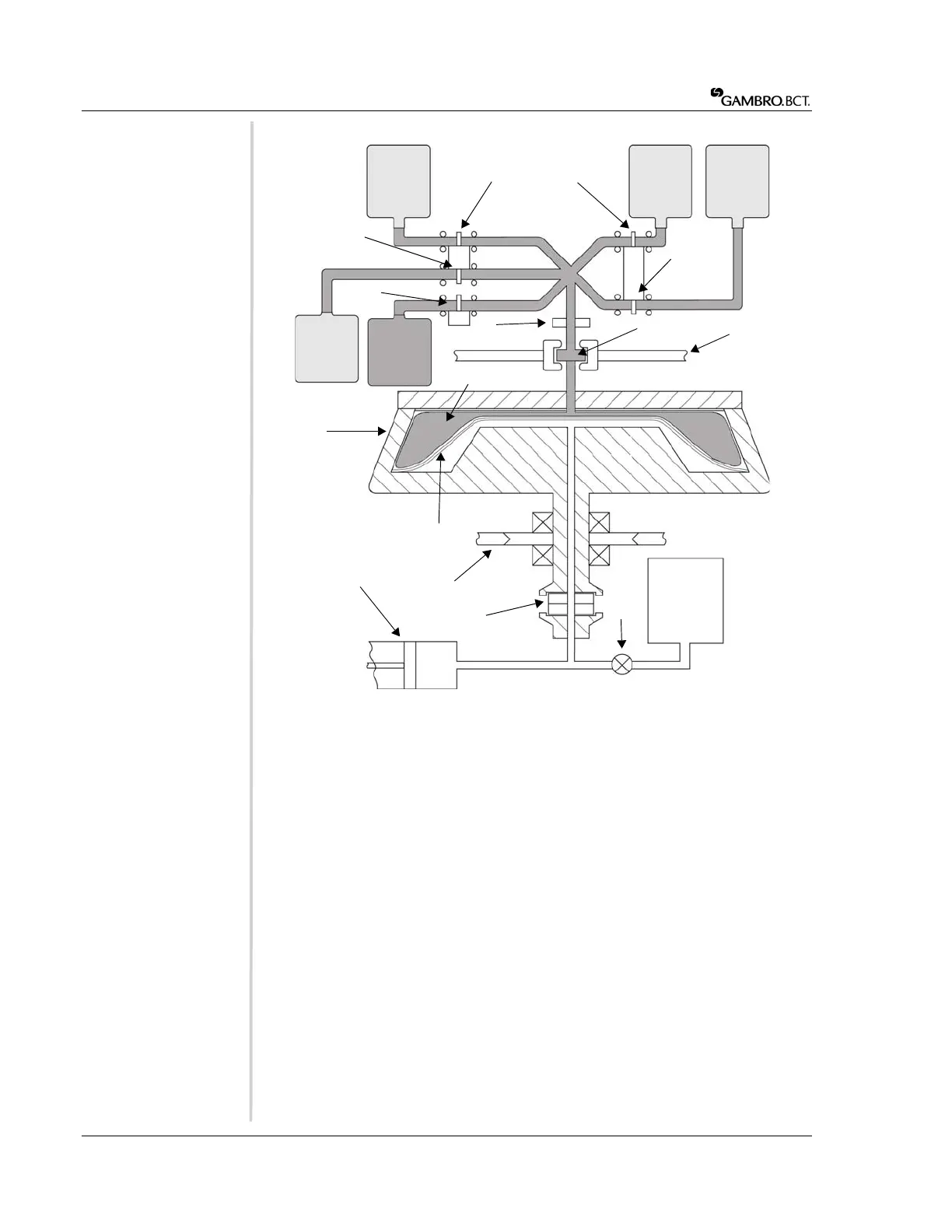
Figure 1-2: Schematic diagram of the COBE 2991 (shaded area indicates cell processing set)
a Cell product bag (starting cell
product)
b Processing/wash solution
c Processing/wash solution
dValve 1 (V1)
eValve 2 (V2)
fValve 3 (V3)
g Collect valve (if applicable)
h Supernatant-out valve (SOV)
i Optional collection bag
j Pre-attached waste collection
bag
k Red cell detector (RCD)
l Rotating seal
m Front and rear sliding covers
n Cell processing bag
o Centrifuge bowl assembly
p Flexible diaphragm
q Centrifuge drive belt
rHydraulic pump
s Ceramic seal
tHydraulic valve
uHydraulic fluid reservoir
a
b
c
d
e
g
f
h
i
j
k
l
m
n
p
q
s
u
r
t
o
 Loading...