System Description
COBE 2991 Cell Processor • Essentials Guide 1-3
Introduction
1
COBE 2991 Components
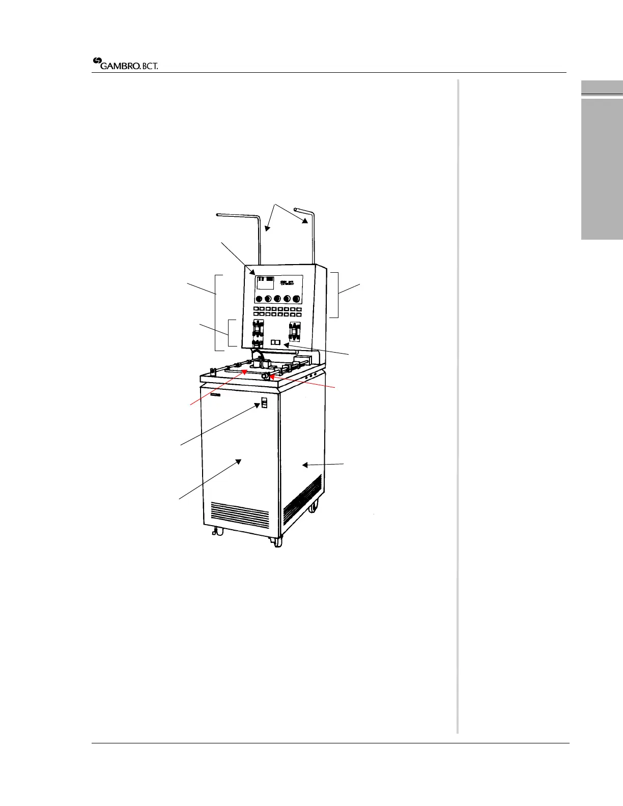
The COBE 2991 (Figure 1-1) consists of an upper and lower section. The upper
section houses the main control panel comprised of the program board, operator
controls, valves, and red cell detector (RCD). The lower section houses the
centrifuge, the hydraulic system, and the secondary control panel.
The schematic diagram on page 1-4 (Figure 1-2) illustrates the COBE 2991’s
operational elements.
Figure 1-1: Locations of major COBE 2991 components (LED version shown)
a Hanger bars
b Program board
c Main control panel
d Operator controls
eValves
f Red cell detector (RCD)
g Tabletop and sliding covers
h Centrifuge cover interlock
latch (newer machines)
iPower switch
j Front panel door
k Secondary control panel (not
pictured)—located behind
right panel door
a
b
c
e
f
g
h
i
j
k
d
 Loading...