Connector Pinouts
190-01810-00 GDL 82 TSO Installation Manual
Rev. 5 Page 5-3
Discrete Inputs*
The GDL 82 has two active-low discrete input pins denoted with an asterisk (*). The following signal conditions are
required for the states of those inputs:
• Active (low) state: Input signal is < 1.0 VDC and/or resistance to ground < 375 ohm
• Inactive (open/high) state: Input signal is between 2.0 VDC and 33 VDC and/or resistance to ground > 130 kilohm
5.2 Functional Descriptions
5.2.1 Power and Antennas
This section provides power input requirements and antenna connections. Refer to section 10 for interconnect
information. The transponder and antenna connections use BNC coaxial connectors. The GPS/SBAS antenna uses a
TNC coaxial connector.
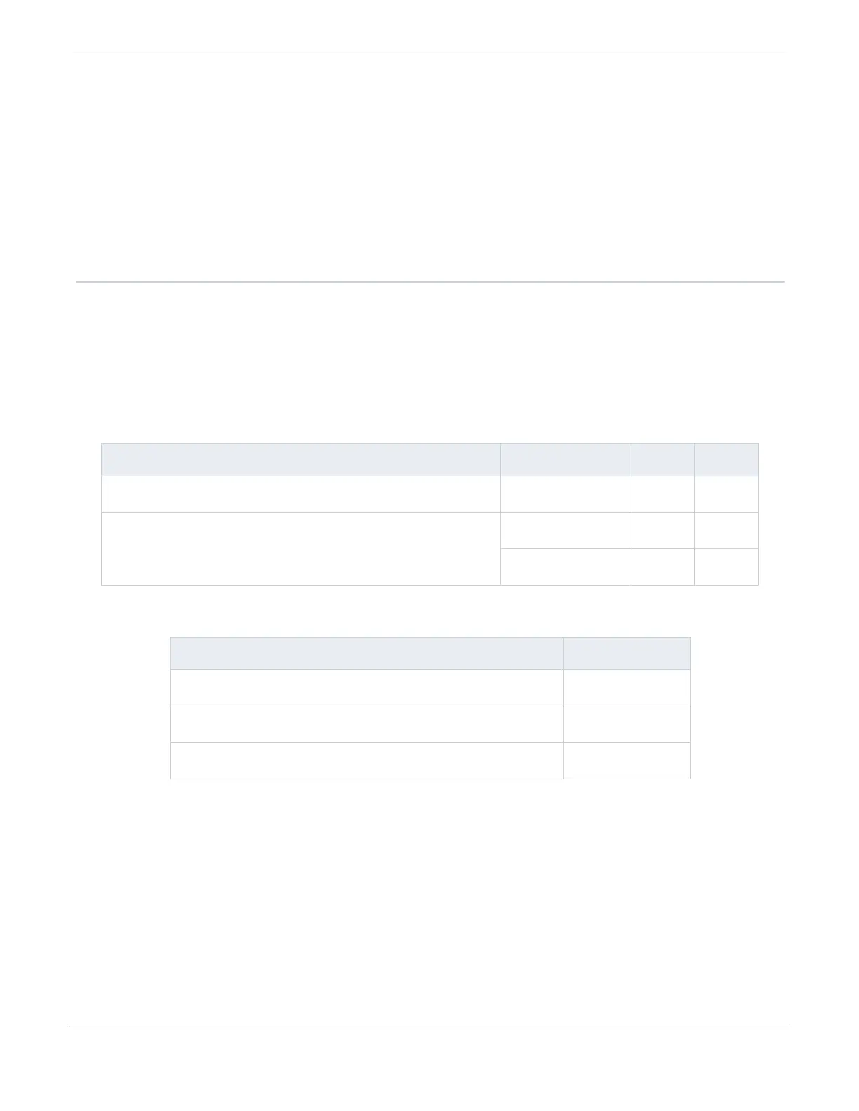
Table 5-2 Power
Table 5-3 Antennas
PIN NAME CONNECTOR PIN I/O
POWER
P821 15 In
GROUND
P821 14 --
P821 7 --
PORT NAME CONNECTOR
TRANSPONDER
XPDR
L-BAND ANTENNA
ANT
GPS/SBAS ANTENNA
GPS

 Loading...


