Installation Procedures
190-01810-00 GDL 82 TSO Installation Manual
Rev. 5 Page 6-8
6.4 Antenna Installation and Connections
The GPS/SBAS installation instructions meet the guidance material contained in AC 20-138D, Airworthiness Approval
of Global Navigation Satellite System (GNSS) Equipment.
6.4.1 GPS Antenna
This section provides information on the GPS/SBAS antenna installation. Refer to section 4.5.2 for installation location
considerations. Refer to GA 35
, GA 36, GA 37 Antenna Installation Instructions for additional installation information.
Temporarily locate the GPS/SBAS antenna with coax connecte
d to the GDL 82 unit and check the GPS/SBAS
performance as described in section 8.1.1. Once a suitable location has been ver
ified, then permanently mount the
antenna.
For RG-142B or RG-400 coaxial cable, 1.5 dB equates to a length of approximately 6.5 feet of cable with a connector
on
each end. RG-142B or RG-400 cable can be used for lengths less than 35 feet. For longer lengths, use low-loss
double or triple shielded 50 ohm coax cable.
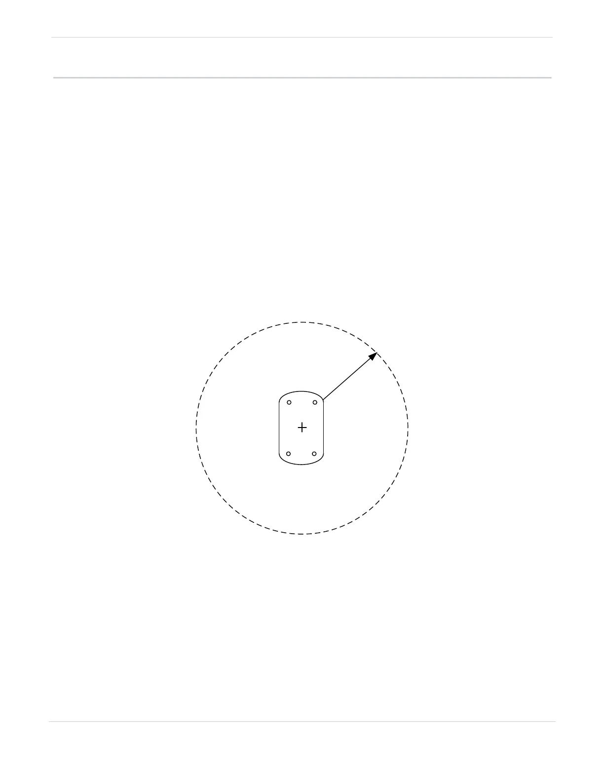
For mounting the antenna, follow the antenna manufacturer’s installation
instructions. Ensure that the GPS/SBAS
antenna is electrically bonded to the aircraft. The GPS/SBAS antenna requires a minimum ground plane radius of
7.5 inches around the perimeter of the antenna.
7.5 IN. MINIMUM
GPS ANTENNA
GROUND PLANE
Figure 6-4 GPS Antenna Ground Plane

 Loading...


