2–28 350 FEEDER PROTECTION SYSTEM – INSTRUCTION MANUAL
ELECTRICAL INSTALLATION CHAPTER 2: INSTALLATION
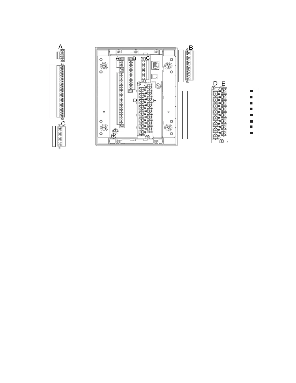
Figure 2-32: 350 Terminal Identification - Non-drawout
Wire range
Use the following guideline when selecting wires or lugs to connect to terminal blocks
A,B,C,D,E (Drawout case design), and terminal blocks D,E (Non-drawout case design):
• 12 AWG to 22 AWG (3.3 mm
2
to 0.3 mm
2
): Single wire termination with/without
9.53
mm (0.375”) maximum diameter ring terminals.
• 14 AWG to 22 AWG (2.1 mm
2
to 0.3 mm
2
): Multiple wire termination with matching
wire sizes and stranding. Two wires maximum per circuit.
• 14 AWG to 22 AWG (2.1 mm
2
to 0.3 mm
2
): Multiple wire termination with 9.53 mm
(0.375”) maximum diameter ring terminals. Two ring terminals maximum per circuit.
• Suggested wiring screw tightening torque, tighten to 12 in-lb (1.35 N-m).
• The uncovered communications cable shield connected to the common terminal
should not exceed 1” (2.5 cm) for proper EMC shielding of the communications cable.
• Minimum suggested temperature rating for the conductors is 75C.
• Wire type: copper
Phase sequence and transformer polarity
For correct operation of the relay features, the user must follow the instrument
transformer polarities, shown in the Typical Wiring Diagram. Note the solid square
markings shown with all instrument transformer connections. When the connections
adhere to this drawing, the arrow shows the direction of power flow for positive watts and
the positive direction of lagging vars. The phase sequence is user programmable for either
ABC or ACB rotation.
INPUT 1
INPUT 2
INPUT 3
INPUT 4
INPUT 5
INPUT 6
INPUT 7
INPUT 8
INPUT 9
INPUT 10
INPUT COM
CHASSIS GND
1
2
3
4
5
6
7
8
9
10
11
12
PHASE A CT
PHASE B CT
PHASE C CT
GND CT
PHASE A VT
PHASE B VT
PHASE C VT
AUX VT
PHASE A CT
PHASE B CT
PHASE C CT
GND CT
PHASE A VT
PHASE B VT
PHASE C VT
AUX VT
5
6
7
8
9
10
11
12
POWER SUPPLY -
POWER SUPPLY +
CHASSIS GND
TRIP COM
CLOSE N/O
CLOSE OPTV
AUX 4 N/C
AUX 4 N/O
AUX 5 COM
AUX 6 N/C
AUX 6 N/O
CRIT FAIL COM
1
2
3
4
5
6
7
8
9
10
11
12
13
14
15
16
17
18
19
20
21
IRIG-B +
IRIG-B -
RS485 +
RS485 -
RS485 COM
CHASSIS GND
RESERVED
RESERVED
1
2
3
4
5
6
7
8
5
6
7
8
9
10
11
12
TRIP N/O
TRIP OPTV
CLOSE COM
AUX 3 N/C
AUX 3 N/O
AUX 4 COM
AUX 5 N/C
AUX 5 N/O
AUX 6 COM
CRIT FAIL N/C
CRIT FAIL N/O
AUX 3 COM
 Loading...


