3–8 350 FEEDER PROTECTION SYSTEM – INSTRUCTION MANUAL
FRONT CONTROL PANEL INTERFACE CHAPTER 3: INTERFACES
Relay messages
Target messages Target messages are automatically displayed for any active condition on the relay such as
pickups, trips, or alarms.
The relay displays the most recent event first, and after 5 seconds will start rolling up the
other target messages until the conditions clear and/or the RESET command is initiated.
The Target Messages can be reviewed by pressing either the MESSAGE UP or MESSAGE
DOWN key. If a RESET command is not performed but any of the other faceplate
pushbuttons is pressed, the display will not show the target messages unless the user
navigates to
ACTUAL VALUES > A4 TARGET MESSAGES, where they can be reviewed. If the
target messages have not been cleared before the user presses a pushbutton different
from “RESET”, they will reappear on the screen after the time specified under the
SETPOINTS > S1 RELAY SETUP > FRONT PANEL > MESSAGE TIMEOUT setting, that will start
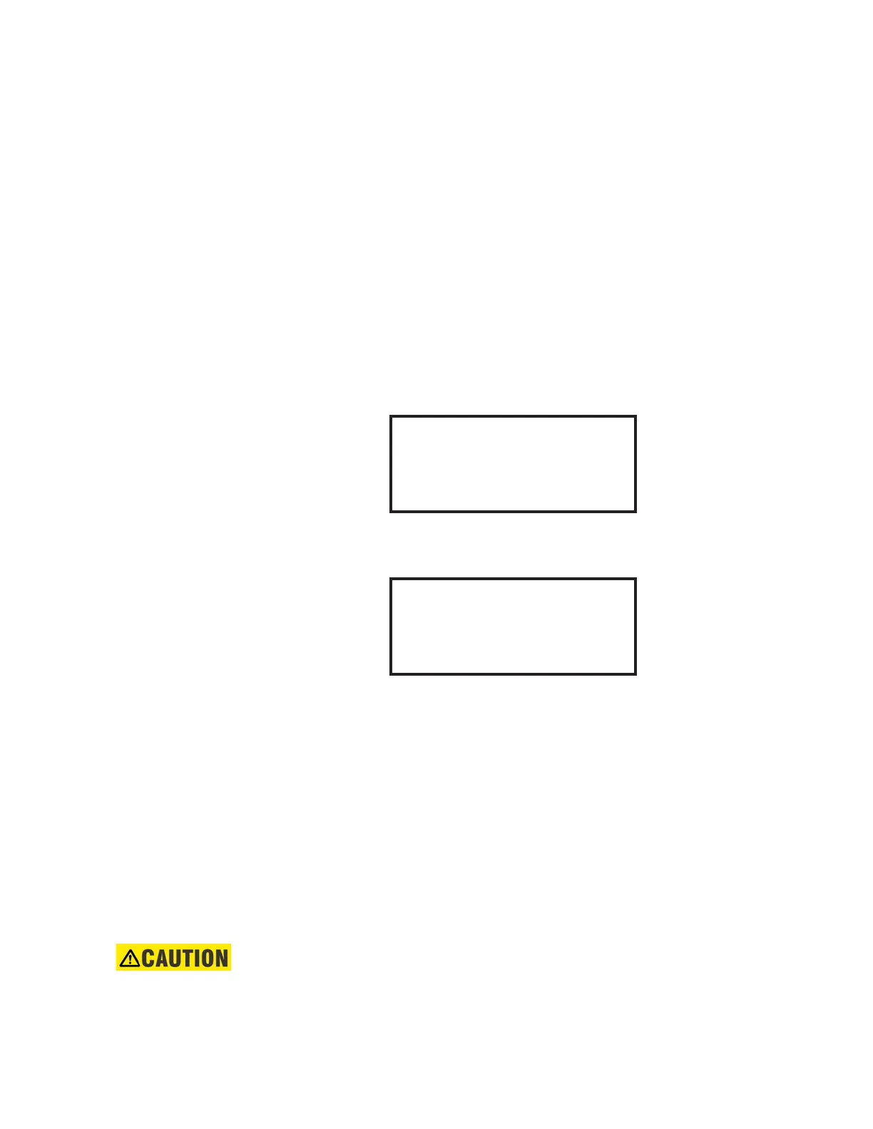
timing out from the last pressed pushbutton. The following shows the format of a typical
Target Message:
Figure 3-5: Typical target message
Example of a Phase IOC1 operation - phase A:
Phase IOC1 function: Trip
Cause <Function>
The first line contains information of the cause of operation (the name of the operated
element), and the element function.
State: Operate
This line from the display shows the state of the element: Pickup, Operated, Alarm.
Phase: A
The last line from the display shows the phase that picked up or operated.
Self-test errors The relay performs self diagnostics at initialization (after power up), and continuously as a
background task to ensure that the hardware and software are functioning correctly.
There are two types of self-test warnings indicating either a minor or major problem. Minor
problems indicate a problem with the relay that does not compromise protection of the
power system. Major errors indicate a problem with the relay which takes it out of service.
CAUTION:
Self-Test Warnings may indicate a serious problem with the relay hardware!
Upon detection of a minor problem, the relay will:
• Turn on the "TROUBLE" LED at the same time as the "IN SERVICE" LED is on.
• Display the error on the relay display.
A4 TARGET MESSAGES
Cause <function>
State: Operate
Phase:
▼
A4 TARGET MESSAGES
Ph IOC1 Trip
State: Operate
Phase:A
▼
 Loading...


