GE Grid Solutions
GE Information 994-0081-3.00-21
Main Board, Continued
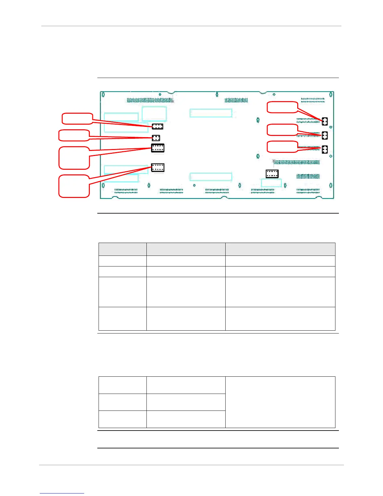
Type III WESDAC board jumpers and their functions:
Board Layout
Drawing
Table: Jumper
Settings
Type III WESDAC board jumper settings.
Jumper Function Default Setting
P5 Factory use only JTAG Connector, Do Not Jumper
P6 Factory use only BDM Connector, Do Not Jumper
JP1 Factory use only, jumper 5 –
6 to enable JTAG for
programming FLASH or
EPLD
No Jumpers on any pins
JP2 Selects EPROM size, and
allows for different FLASH
memory options
Pins 3 – 5 shorted: 256K EPROM
Pins 5 – 7 shorted: 512K EPROM
Backward
Compatibility
Jumpers
The following table shows the jumper setting for backward compatibility.
These jumpers cannot set the wetting voltage source of the CE Mark
digital input cards. (The wetting voltage must be routed externally for the
CE Mark cards.)
JP3 Wetting for Low Voltage DI
card #1
Pin 3 – 5 and 4 – 6 shorted: External or
D25 power supply
Pins 3 – 4 shorted: Voltage Sense
Note: These jumpers not used with
High Voltage DI Cards
JP4 Wetting for Low Voltage DI
card #2
JP5 Wetting for Low Voltage DI
card #3
Reset Switch
The Type III WESDAC board does not have a “slide” reset switch.
BDM
JTAG

 Loading...


