GE Grid Solutions
GE Information 994-0081-3.00-21
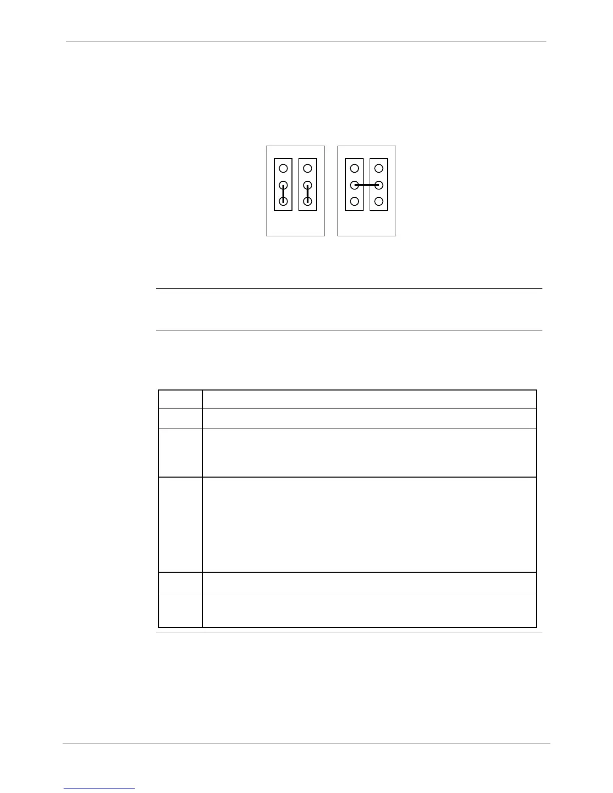
Main Board, Continued
Type III
WESDAC
Wetting
Jumper Detail
(Backward
Compatibility)
Jumpers shown are for the first (top) 32-point module. Jumpers (J4 and J3)
for the other two modules work in the same way.
External or
Supplied Wetting
Note: Supplied wetting voltage is 24 or 48 Volts: depends on power supply
used.
Note
Supplied Wetting option is not available if the Graphics Display panel is
installed.
Procedure:
Board
Replacement
How to replace the WESDAC Board:
Step Action
1 Hold the mounting brackets at each side of the module.
2 Tilt the card slightly, and insert the top first, ensuring that the
battery connections do not come into contact with the metal
housing.
3 Carefully position the board so that:
− the alignment pins align with the holes at the top and bottom of
the WESDAC Board
− the captive screws align with their holes
− the female connectors on the rear of the WESDAC Board align
with the male connectors of other boards
4 Press the WESDAC Board firmly into position.
5 Tighten all the mounting screws to ensure the WESDAC Board
connectors are firmly attached and the board is grounded.

 Loading...


