GE Grid Solutions
994-0081-3.00-21 GE Information
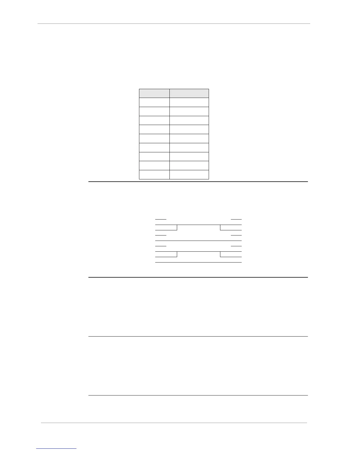
Communications Ports, Continued
Table: D25
MAINT Port
Pinout
Pinout of the D25 MAINT DB-9 connector.
DB-9 Pin RS-485
1 N/C
2 RX-
3 TX-
4 N/C
5 Com GND
6 N/C
7 TX+
8 RX+
9 EARTH GND
2-Wire RS-485
Cable
Schematic of the cable wiring necessary for 2-Wire RS-485 connection.
Description PIN # PIN # Description
1
2
3
4
5
6
7
8
9
1
2
3
4
5
6
7
8
9
N/C
Data -
Data -
N/C
Common Ground
N/C
Data +
Data +
Earth Ground
N/C
Data -
Data -
N/C
Common Ground
N/C
Data +
Data +
Earth Ground
COM2
Universal Time
Code (UTC)
Port
The Universal Time Code (UTC) port located on the back panel provides a
connection to a satellite time-code receiver, or equivalent.
• The DB-9-F UTC port can be selected for receive-only RS-232 or RS-422
interface, using SGConfig.
• Supported UTC Port protocols are IRIG-B and Rugby
• Communication parameters are determined by the protocol application.
Note
Many IRIG-B receivers are available with modulated and/or unmodulated
output options.
• IRIG-B is received on CTS port.
• The input to the UTC port must be unmodulated.
• If the unmodulated output of the receiver is a coaxial connection, a converter
will be required to interface the D25.

 Loading...


