GE Grid Solutions
GE Information 994-0081-3.00-21
Communications Ports, Continued
Table: UTC
Port Pinout
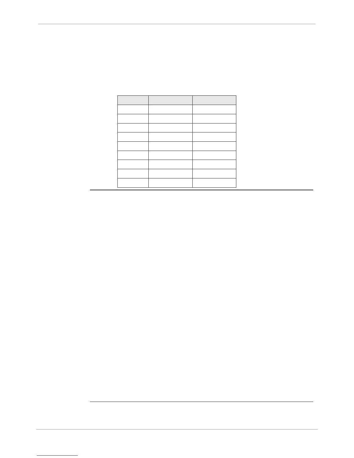
How to connect to the UTC Port DB-9 connector for either RS-232 or RS-422
interface.
Note: Pins 7 and 8 are tied together internally.
DB-9 Pin RS-422 Signal RS-232 Signal
1 T_RX+ N/C
2 T_RX- RX
3 N/C N/C
4 N/C N/C
5 COM GND COM GND
6 CLKE+ N/C
7 CLKE- N/C
8 N/C CTS
9 EARTH GND EARTH GND
COM3 and
COM4
IED1 and IED2
Serial Ports
Two general-purpose, on-board communication ports are available on the
back panel of the D25, and use female DB-9-F style connectors. The IED
ports provide:
• Variable communication parameters
• Optional software flow control
• Optional hardware flow control
• Out-of-sequence transmission of one byte of data
• Support for several I/O timers
Transmission of break characters
Both IED ports RS-232 and RS-485 (for multi-drop applications) are
supported on the same physical connector.
Note: The input resistance 12 KΩ is used for all serial ports in D25
(UTC/IED/XCOM) when configured as RS485. The typical resistance
is 24 KΩ, but use 12 KΩ as maximum burden. This is very important
for daisy chaining D25s, especially for IRIG-B signals.
IED Serial
Ports Options
The COM3 and COM4 serial ports are programmed via SGConfig for:
− RS-232 or RS-485 selection
− RS-485 2-Wire / 4-Wire selection
Note: The 2 to 4- Wire selection in SGConfig Device Properties only
affects the internal software control (handshaking) of the interface.
It does not change the physical characteristics of the communication
ports.

 Loading...


