– 37 –
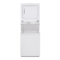
The gas valve is attached to a bracket located in
the bottom, right, front corner of the dryer cabinet.
Gas Valve Removal
1. 6KXWRႇWKHJDVVXSSO\WRWKHXQLW
2. 'LVFRQQHFWWKHÀH[LEOHPHWDOFRQQHFWRUIURP
the burner inlet pipe.
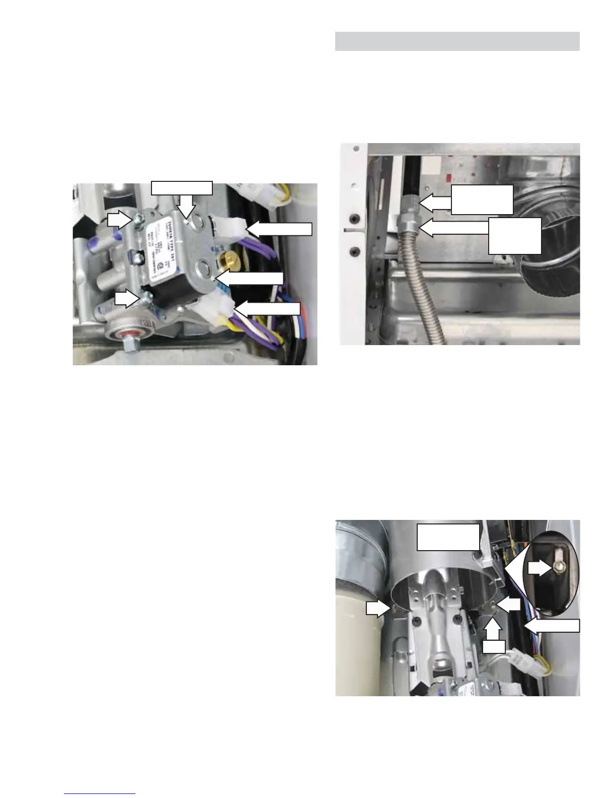
3. Remove the drum. (See Drum in this section
of this service guide.)
4. Remove the two 1/4-in. hex-head screws that
attach the combustion chamber to the dryer
ÀRRU
5. Remove the 1/4-in. hex-head screw, located
XQGHUQHDWKWKHÀDPHGHWHFWRUWKDWDWWDFKHV
the gas valve inlet pipe to the dryer chassis.
NOTE: Upon reassembly, ensure the tab at the
bottom of the combustion chamber is inserted
into the slot located on the dryer chassis.
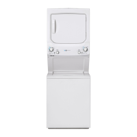
Double and Main Coils Removal
1. Remove the drum. (See Drum in this section
of this service guide.)
2. Disconnect the wire harness from both coils.
3. Note the position of the locator pins inserted
in the coil bracket.
4. Remove the two Phillips-head screws that
attach the coil bracket to the valve body.
5. Lift the bracket vertically. Lift coils to remove.
NOTE: Upon reassembly, ensure the locator pins
are inserted into the holes provided in the coil
bracket.
Locator Pin
Disconnect
Disconnect
Locator Pin
Flexible
Metal
Connector
Burner Inlet
Pipe
Inlet Pipe
Combustion
Chamber
Slot
Gas Valve
(Continued Next Page)
 Loading...