– 48 –
'LDJQRVLQJWKHMode Shifter Switch
The Mode Shifter Switch's home position is
closed, ready for a spin cycle. When agitating,
the switch should be open. From the J512
connector on the control board, the tan wire pin 5
to the J511 connector pin 4 (JUD\ wire).
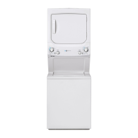
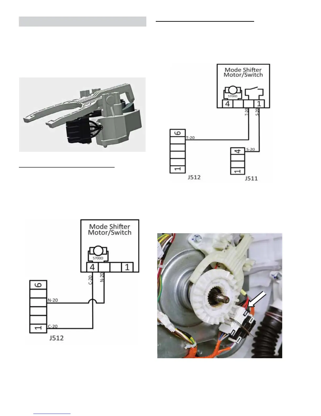
Mode Shifter Removal
The belt protector, belt and transmission pulley
need to be removed to access the mode shifter.
1. Disconnect the mode shifter motor harness
connector.
2. Remove two 3/8-in. hex-head bolts securing
the mode shifter to the platform. The mode
VKLIWHUFOXWFKFOXWFKVSULQJDQGÀDWZDVKHU
will pull away from the platform.
The mode shifter consists of a motor that
operates by receiving 120 VAC from the control
board, a micro switch, and a spring and clutch.
It engages or disengages the clutch with the
transmission pulley, depending on whether the
cycle is in spin or agitate.
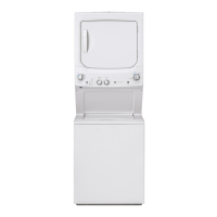
'LDJQRVLQJWKHMode Shifter Motor
From the J512 connector on the control board,
the brown wire pin 1 to the blue wire pin 4 should
read approximately 5700 ohms. The 120 VAC
can be applied to the motor two black wires on
the mode shifter to manually check mode shifter
operation.
Mode Shifter
 Loading...