– 46 –
Pin 1 to pin 5 should read approximately 4.5
VDC while rotating the basket by hand.
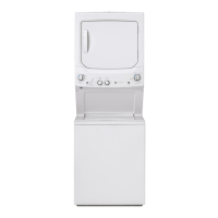
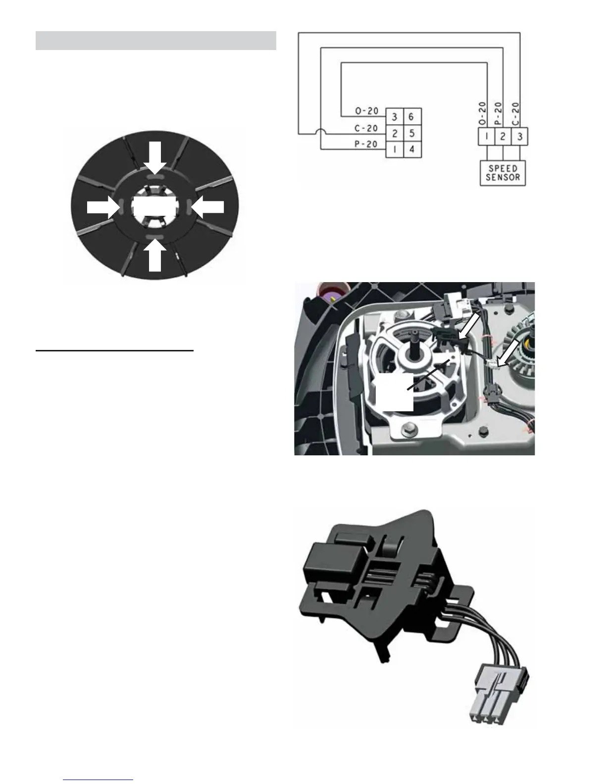
Speed/Hall Sensor Removal
Disconnect the speed/hall sensor from the drive
motor and disconnect from the main harness.
There is a locating post on the bottom of the
sensor that is pushed into an existing hole in the
motor housing, when reinstalling.
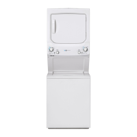
The speed/hall sensor is mounted to the drive
motor and sends a pulse signal back to the
control board. This is done when the magnet that
is mounted in the drive motor pulley passes over
the sensor.
If the control does not read any signal from the
sensor from the movement of the motor, the
washer cycle will stop.
6SHHG+DOO6HQVRU'LDJQRVLQJ
The speed/hall sensor can be diagnosed two
GLႇHUHQWZD\V
Enter the Service Mode and Run the Spin
Test
If the speed/hall sensor is bad or
disconnected, the basket will start to spin
QRUPDOO\DW¿UVW$IWHUVHFRQGVPRWRU
power will be stopped and a locked rotor fault
will be set. If the washer continues to spin for
at least 15 seconds, the speed/hall sensor is
good.
7HVWWKH9ROWDJH
From connector pins 3 to 5 on the J602
should read approximately 9 VDC.
Magnet
Guide
post
hole
Speed/Hall Sensor
 Loading...