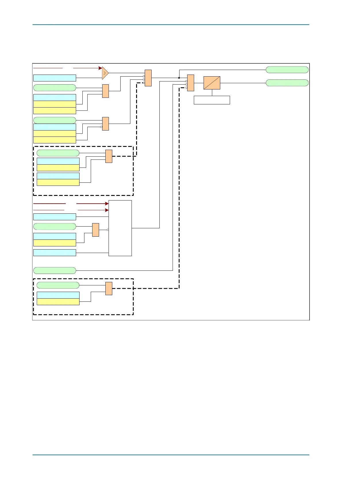
3.3.1 DIRECTIONAL OVERCURRENT LOGIC
I>1 Timer Block
V00602
Blinder Function
3Ph(based on Z 1)
Z1 LoadBlinder
I> Blocking 2
Blinder Blk I>1
VTS Fast Block
I> Blocking
VTS Blocks I>1
Directional
check
I>1 Direction
I>1 Start A
I>1 Trip A
IA2H Start
I> Blocking
2H Blocks I>1
2H 1PH BLOCK
I>1 Current Set
&
IDMT/DT
Timer Settings
&
I2H Any Start
I> Blocking
2H Blocks I>1
2H 1PH BLOCK
&
&
&
&
Notes: This diagram does not show all stages . Other stages follow
similar principles.
This diagram does not show all phases . Other phases follow
similar principles.
Load blinder functionality is only available for stages 1, 2 and 5
and on selected directional models .
AR blocking is only available for stages 3, 4 and 6
AR Blk Main Prot
I> Blocking
AR Blocks I>3
&
AR blocking available for DT-only stages
Load Blinder blocking available for stages 1, 2 and 5
I> Char Angle
IA
IA
VAB
Figure 35: Directional Overcurrent Logic diagram (Phase A shown only)
Voltage Transformer S
upervision (VTS) can be used to block operation of directional overcurrent elements.
This is achieved using the I>Blocking cell. When the relevant bit is set to 1, operation of the VTS will block the stage
if directionalised. When set to 0, the stage will revert to non-directional upon operation of the VTS.
P14x Chapter 6 - Current Protection Functions
P14xEd1-TM-EN-1 101
 Loading...


