K1
Op
erate region
Is1
Ib
ias
Idiff
V00678
Restraint region
K2
Is1/K1 Is2
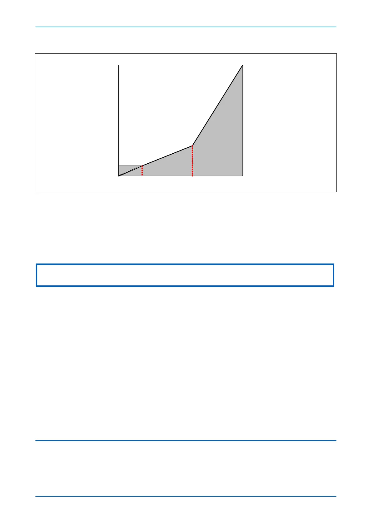
Figure 94: REF bias characteristic
The following settings are provided to define this bias characteristic:
● IREF> Is1: sets the minimum trip threshold
● IREF> Is2: sets the bias current kneepoint whereby the required trip current starts increasing
● IREF> k1: defines the first slope (often set to 0%)
● IREF> k2: defines the second slope
Note:
Is1 and Is2 are relative to the line CT, which is always the reference CT.
3.2.2 DELAYED BIAS
The bias quantity used is actually delayed by one cycle. It is the maximum value of the mean bias quantities
calculated within the previous cy
cle, where the mean bias is the fundamental bias current. This means the bias
level, and thus through-fault stability is maintained after an external fault has been cleared.
The algorithm, shown below, is executed eight times per cycle.
I
bias
= Maximum [I
bias
(n), I
bias
(n-1), …I
bias
, (n – (K-1))]
It is this delayed bias that is used to calculate the operating current.
3.2.3 TRANSIENT BIAS
If there is a sudden increase in the mean-bias measurement, an additional bias quantity is introduced in the bias
calculation. Transient Bias pr
ovides stability for external faults wher
e CT saturation might occur.
The transient bias function enhances the stability of the differential element during external faults and allows for
the time delay in CT saturation caused by small external fault currents and high X/R ratios.
No transient bias is produced under load switching conditions, or when the CT comes out of saturation.
3.3 HIGH IMPEDANCE REF
The device provides a high impedance restricted earth fault protection function. An external resistor is required to
provide stability in the pr
esence of saturated line current transformers. Current transformer supervision signals do
Chapter 7 - Restricted Earth Fault Protection P14x
172 P14xEd1-TM-EN-1
 Loading...


