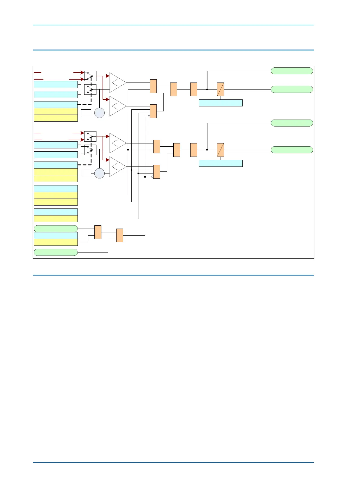
3.2 UNDERPOWER LOGIC
Power<1 A Trip
Power<1 Mode
V00901
Power<1 A Start
Power<1 3Ph Trip
Power<1 3PhStart
V<1 Poledead Inh
Enabled
VTS Slow Block
All Poles Dead
Power<1 1Ph Watt
Power<1 1Ph VAR
&
Power<1 Status
Enabled
&
Power<1Direction
Forward
&
1
Reverse
X-1
Active
Reactive
Power<1 Mode
Power<1 3Ph Watt
Power<1 3Ph VAR
X-1
Active
Reactive
DT
Power>1TimeDelay
Power>1TimeDelay
Note: This diagram does not show all stages . Other stages follow similar principles.
DT&
&1
&
1
&
A Phase Watts
3 Phase Watts
A Phase VA
3 Phase VA
Figure 138: Underpower logic
3.3 APPLICATION NOTES
3.3.1 LOW FORWARD POWER CONSIDERATIONS
The Low Forward Power protection can be arranged to interlock ‘non-urgent’ protection tripping using the
pr
ogrammable scheme logic. It can also be arranged to pr
ovide a contact for external interlocking of manual
tripping. To prevent unwanted alarms and flags, a Low Forward Power protection element can be disabled when
the circuit breaker is opened via Pole Dead logic.
The Low Forward Power protection can also be used to provide loss of load protection when a machine is
motoring. It can be used for example to protect a machine which is pumping from becoming unprimed, or to stop
a motor in the event of a failure in the mechanical transmission.
A typical application would be for pump storage generators operating in the motoring mode, where there is a need
to prevent the machine becoming unprimed which can cause blade and runner damage. During motoring
conditions, it is typical for the protection to switch to another setting group with the low forward power enabled
and correctly set and the protection operating mode set to Reverse.
A low forward power element may also be used to detect a loss of mains or loss of grid condition for applications
where the distributed generator is not allowed to export power to the system.
3.3.2 LOW FORWARD POWER SETTING GUIDELINES
Each stage of power protection can be selected to operate as a forward power stage by selecting the P
ow
er<(n)
Direction cell to Forward.
Chapter 12 - Power Protection Functions P14x
264 P14xEd1-TM-EN-1
 Loading...


