The VH1 and IH2 components are passed through a sign filter and multiplied to create a reactive power
component in the range of -1 to +1. This is the transient reactiv
e power Q
tran
. If Q
tran
> 0, then there forward line is
healthy. If Q
tran
< 0, then the forward line is faulty.
There are two modes of operation for the direction detector; Standard and Advanced. Standard mode is used in
most cases and is described here. Advanced mode is for special situations, and involves dynamically altering the
Q
tran
thresholds. For details of Advanced mode, please contact General Electric.
The inputs to this module are:
● The residual voltage
● The residual current
● Dir> Vnf Thresh (defines the threshold for the residual voltage sign filter).
● Dir> Inf Thresh (defines the threshold for the residual current sign filter
The DD outputs two signals to indicate a forward fault and a reverse fault
Sign Filter Thresholds
The Dir> Vnf Thresh setting is used to get the sign of instantaneous voltage value by sign filter. If the input value is
larger than Vnf, the output is +1. If the input value is less than -1*Vnf, the output is -1. Otherwise the output is 0.
The Dir> Inf Thresh setting is used to get the sign of instantaneous current value by sign filter. If the input value is
larger than Vnf, the output is +1. If the input value is less than -1*Vnf, the output is -1. Otherwise the output is 0.
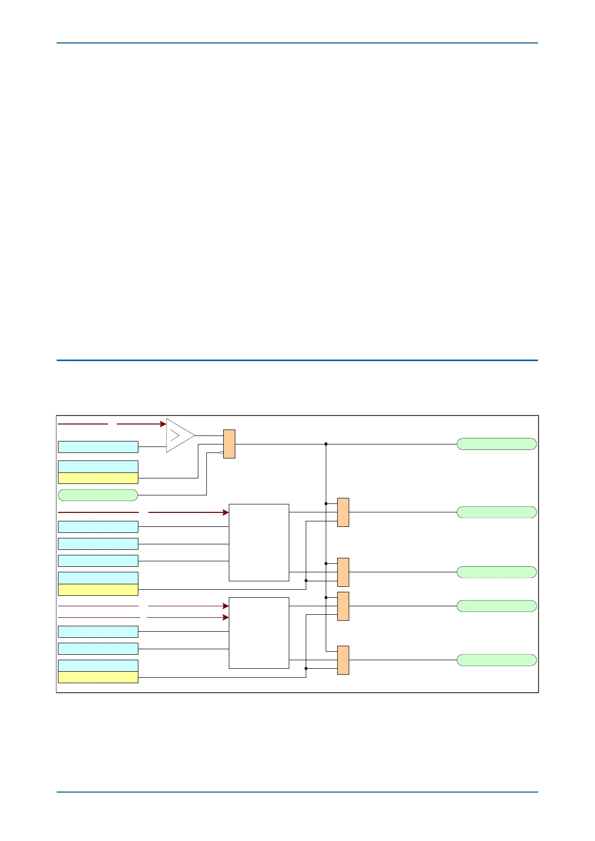
5.2 TRANSIENT EARTH FAULT DETECTION LOGIC
5.2.1 TRANSIENT EARTH FAULT DETECTION LOGIC OVERVIEW
VN
V00905
TEF> Start
TEF VN> Start
TEF Detection
Enabled
TEF> Timer Block
VN
Dir>Vnf Thresh
IN
Dir>Inf Thresh
TRP
Direction
Detector Module
Forward
Reverse
&
&
&
TEF>DIR FWD
TEF>DIR REV
TEF> Steady
TEF> Intermit
TEF>Dir Status
Enabled
FA
Fault Type
Detector Module
Steady
Intermittent
FTD> Time Window
FTD> Fault Count
FTD> Status
Enabled
&
&
VN
FTD> VN
Figure 141: Transient Earth Fault Logic Overview
Chapter 12 - Power Protection Functions P14x
272 P14xEd1-TM-EN-1
 Loading...


