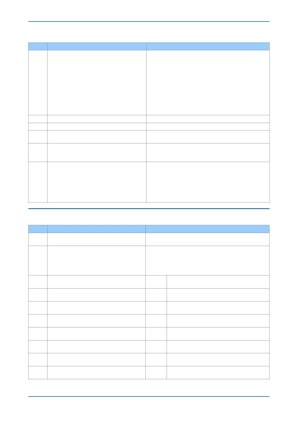
Test Check Action
3
Error Code Identification
The following text messages (in English) are display
ed if a
fundamental problem is detected, preventing the system
from booting:
Bus Fail – address lines
SRAM Fail – data lines
FLASH Fail format error
FLASH Fail checksum
Code Verify Fail
The following hex error codes relate to errors detected in
specific IED modules:
These messages indicate that a problem has been detected on the IED’s
main processor board in the front panel.
3.1 0c140005/0c0d0000 Input Module (including opto-isolated inputs)
3.2 0c140006/0c0e0000 Output IED Cards
3.3 The last four digits provide details on the actual error.
Other error codes relate to hardware or software problems on the main
processor board. Contact with details of the problem for a full analysis.
4
The IED displays a message for corrupt settings and
prompts for the default values to be restored for the
affected settings.
The power-up tests have detected corrupted IED settings. Restore the
default settings to allow the power-up to complete, and then reapply
the application-specific settings.
5
The IED resets when the power-up is complete. A record
error code is displayed
Error 0x0E080000, programmable scheme logic error due to excessive
execution time. Restore the default settings by powering up with both
horizontal cursor keys pressed, then confirm restoration of defaults at
the prompt using the Enter key. If the IED powers up successfully, check
the programmable logic for feedback paths.
Other error codes relate to software errors on the main processor
board.
3.4 OUT OF SERVICE LED ON AT POWER-UP
Test Check Action
1
Using the IED menu, confirm the Commission Test or Test
Mode setting is Enabled. If it is not Enabled, go to test 2.
If the setting is Enabled, disable the test mode and make sure the Out of
Service LED is OFF
.
2
Select the VIE
W REC
ORDS column then view the last
maintenance record from the menu.
Check for the H/W Verify Fail maintenance record. This indicates a
discrepancy betw
een the IED model number and the hardware. Examine
the Maint Data; cell. This indicates the causes of the failure using bit
fields:
Bit Meaning
0
The application type field in the model number does not
match the softw
ar
e ID
1
The application field in the model number does not match
the softwar
e ID
2
The variant 1 field in the model number does not match the
softwar
e ID
3
The variant 2 field in the model number does not match the
softwar
e ID
4
The protocol field in the model number does not match the
softwar
e ID
5
The language field in the model number does not match the
softwar
e ID
6
The VT type field in the model number is incorrect (110 V VTs
fitted)
7
The VT type field in the model number is incorrect (440 V VTs
fitted)
P14x Chapter 22 - Maintenance and Troubleshooting
P14xEd1-TM-EN-1 525
 Loading...


