The single phase mode uses the normal impedance (Z) of each phase. When single phase mode is selected, the
over
current blocking is phase segregated and is dependant on the individual overcurrent settings per phase. In
single phase mode, only the undervoltage threshold (Blinder V< Block) can block the function.
The three phase mode uses positive sequence impedance (Z1). The three phase mode uses both the negative
sequence overcurrent threshold (Blinder I2>Block) and the undervoltage threshold (Blinder V< Block) to block the
function.
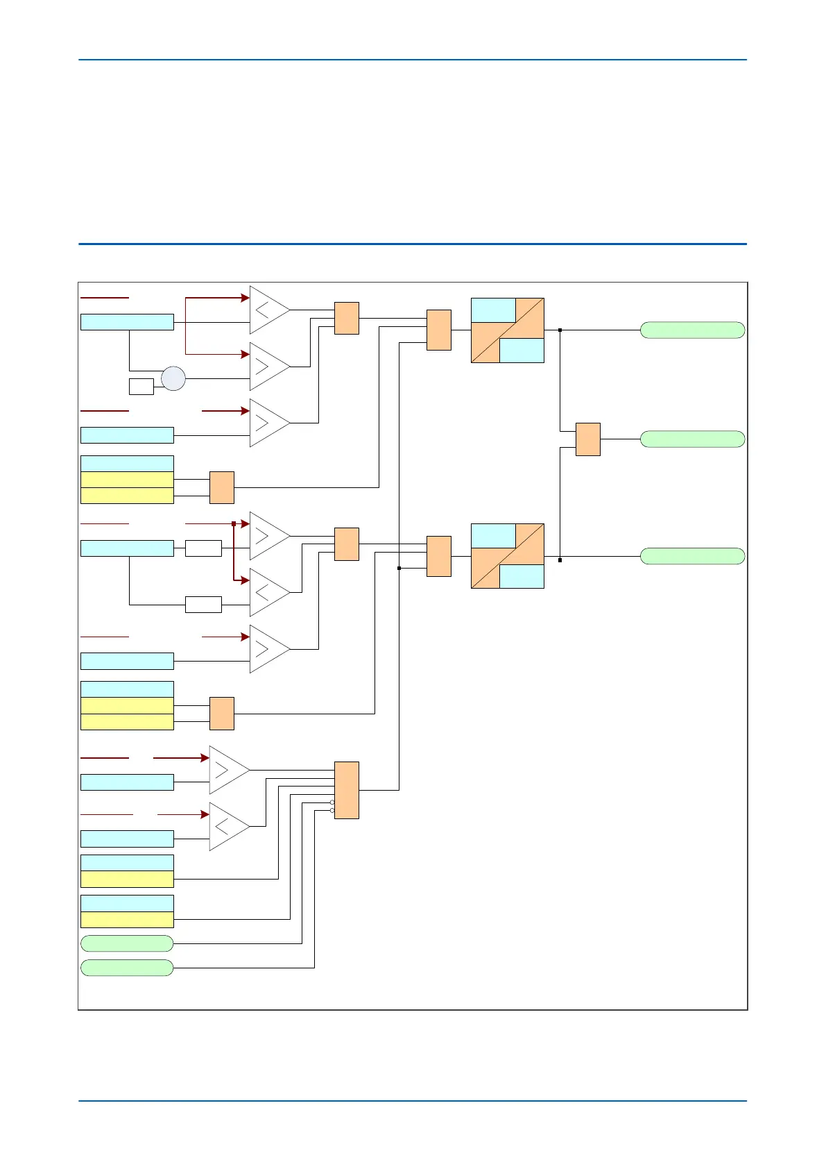
16.2 LOAD BLINDER LOGIC
Z1 FWD Blinder
Z1 LoadBlinder
FWD Z Angle
&
FWD Z Impedance
1
V00650
Drop off
Cycles
Pick up
Cycles
-1
X
Blinder Mode
Forward
1
Both
Z1 REV Blinder
REV Z Angle
&
REV Z Impedance
Drop off
Cycles
Pick up
Cycles
+180°
Blinder Mode
Reverse
1
Both
-180°
&
&
Blinder Function
3ph(based on Z 1)
Blinder Status
Enabled
Blinder V< Block
Blinder I2<Block
VTS Slow Block
CTS Block
&
Z1 Angle
Z1 Magnitude
Z1 Angle
Z1 Magnitude
V1
I2
Figure 79: Load Blinder logic 3phase
P14x Chapter 6 - Current Protection Functions
P14xEd1-TM-EN-1 153
 Loading...


