4.3 APPLICATION NOTES
4.3.1 SETTING GUIDELINES
Following changes on the network caused by faults or other operational requirements, it is possible that various
subsystems will be formed within the power netw
ork. It is likely that these subsystems will suffer from a
generation/load imbalance. The "islands" where generation exceeds the existing load will be subject to
overfrequency conditions. Severe over frequency conditions may be unacceptable to many industrial loads, since
running speeds of motors will be affected. The overfrequency element can be suitably set to sense this
contingency.
An example of two-stage overfrequency protection is shown below using stages 5 and 6 of the f+t elements.
However, settings for a real system will depend on the maximum frequency that equipment can tolerate for a
given period of time.
Stage Element Frequency Setting (Hz) Time Setting (Sec.)
1 Stage 5(f+t) 50.5 30
2 Stage 6(f+t) 51.0 20
The relatively long time delays are intended to provide time for the system controls to respond and will work well in
a situation where the incr
ease of system frequency is slow.
For situations where rapid increase of frequency is expected, the protection scheme above could be supplemented
by rate of change of frequency protection elements.
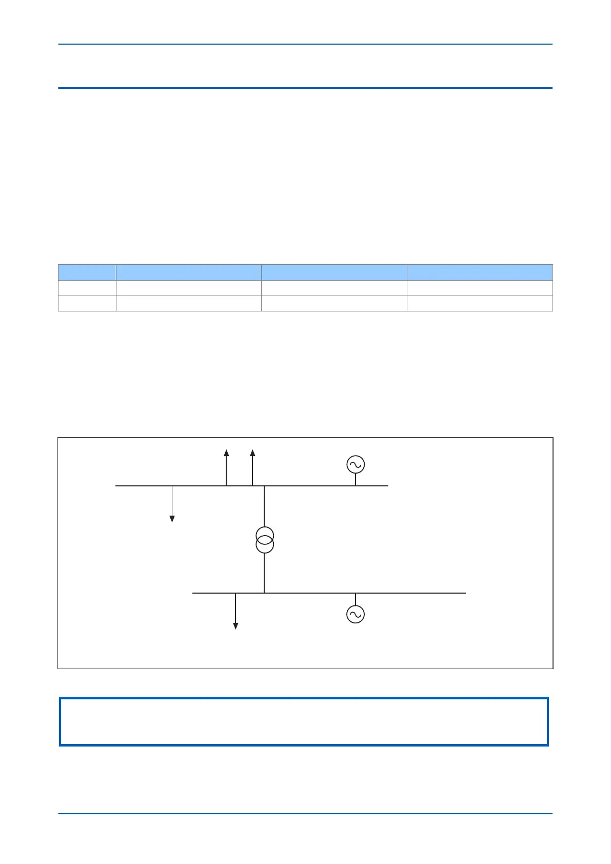
In the system shown below, the generation in the MV bus is sized according to the loads on that bus, whereas the
generators linked to the HV bus produce energy for export to utility. If the links to the grid are lost, the generation
will cause the system frequency to rise. This rate of rise could be used to isolate the MV bus from the HV system.
E00857
Load
Load
To utility
Local generation
IPP
generation
HV bus
MV bus
Figure 128: Power system segregation based upon frequency measurements
Note:
This section r
efers to advanced frequency protection. The basic frequency protection works in a similar manner, but the
setting names and DDB signal names are different.
P14x Chapter 11 - Frequency Protection Functions
P14xEd1-TM-EN-1 241
 Loading...


