E01204
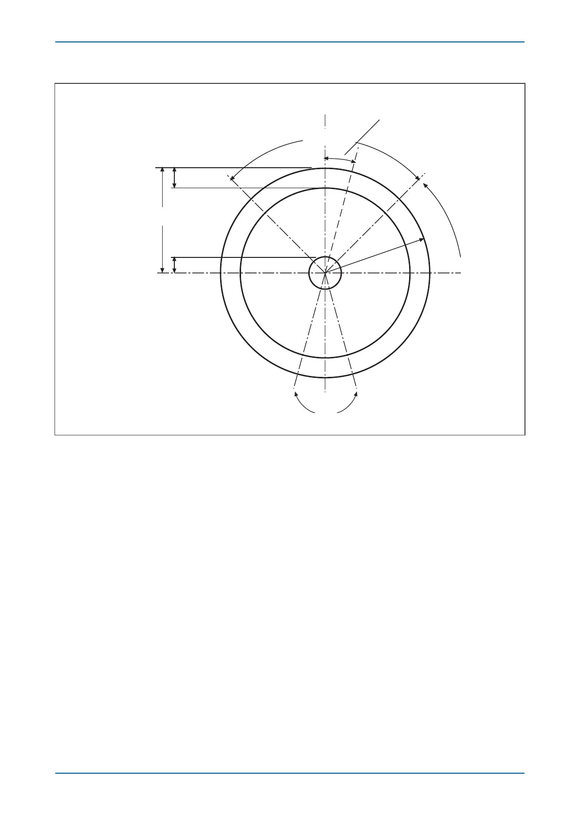
Live Volts
Nomical
Volts
Dead Volts
Check Sync
Stage 2 Limits
Rotating
Vector
±180º
System Split
Limits
V
LINE
Check Sync
Stage 1 Limits
0º
V
BUS
Figure 168: Check Synchronisation vector diagram
9.1.5 SYSTEM SPLIT
If the line side and bus side are of the same frequency (i.e. in synchronism) but have a large phase angle between
them (180° +/- the set limits), the system is said to be 'Split
'. If this is the case, the device will detect this and issue
an alarm signal indicating this.
The settings specific to System Split functionality are found under the sub-heading SYSTEM SPLIT in the SYSTEM
CHECKS column.
Chapter 14 - Monitoring and Control P14x
332 P14xEd1-TM-EN-1
 Loading...


