8.3 LOAD RESTORATION LOGIC
V00860
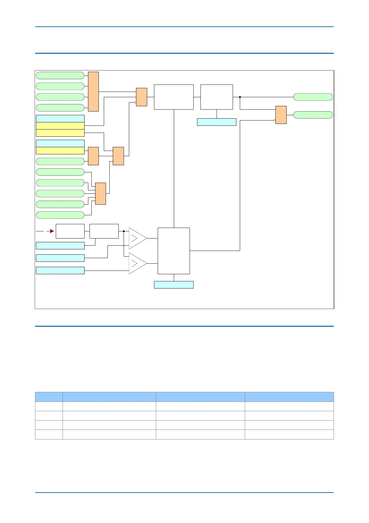
Stg1 f+t Trp
Stg1 df/dt+t Trp
Stg1 f+df/dt Trp
Stg1 f+Df/Dt Trp
1
Load Restoration
Function
Adv Freq Inh
Freq Not Found
Stg1 Block
Freq High
Freq Low
1
V<B Status
Enabled
UV Block
1 1
Restore1 Status
Disabled
Enabled
&
V
Frequency
Averaging
Restore1 Freq
Freq Avg.Cycles
Frequency
determination
Holding Timer 1
Highest Freq setting
Holding function
Cumulative
Timer
Restore1 Time
Stg1 Restore Sta
Stg1 Restore Cls
&
Note: This diagram does not show all stages . Other stages follow similar principles.
Figure 136: Load Restoration logic
8.4 APPLICATION NOTES
8.4.1 SETTING GUIDELINES
A four stage, single frequency load restoration scheme is shown below. The frequency setting has been chosen
such that ther
e is sufficient separation betw
een the highest load shed frequency and the restoration frequency to
prevent any possible hunting. A restoration frequency setting closer to nominal frequency may be chosen if an
operating frequency of 49.3 Hz is unacceptable.
Stage Restoration Frequency Setting (Hz) Restoration Time Delay (secs) Holding Time Delay (secs)
1 49.3 Hz 240 sec 20 sec
2 49.3 Hz 180 sec 20 sec
3 49.3 Hz 120 sec 20 sec
4 49.3 Hz 60 sec 20 sec
In this scheme, the time delays ensure that the most critical loads are reconnected (assuming that the higher
stages refer to mor
e important loads). By restoring the load sequentially, system stability should normally be
Chapter 11 - Frequency Protection Functions P14x
254 P14xEd1-TM-EN-1
 Loading...


