Note:
Although the start point of the charact
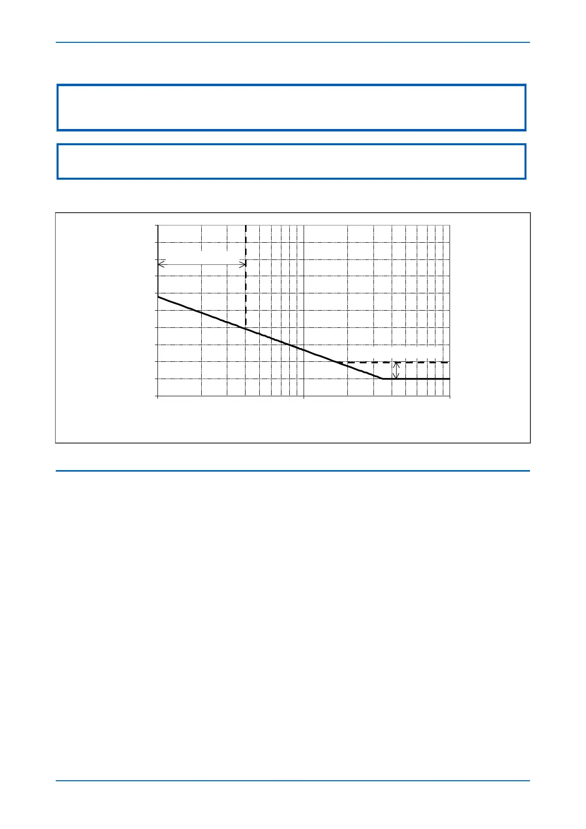
eristic is defined by the "ΙN>" setting, the actual current threshold is a different setting
called "IDG Ιs". The "IDG Ιs" setting is set as a multiple of "ΙN>".
Note:
When using an IDG Operate charact
eristic, DT is always used with a value of zero for the Rest characteristic.
An additional setting "IDG Time" is also used to set the minimum operating time at high levels of fault current.
V00611
IDG Time Setting Range
IDG Is Setting Range
O
p
e
r
a
t
i
n
g
t
i
m
e
(
s
e
c
o
n
d
s
)
Figure 49: IDG Characteristic
10.4 DIRECTIONAL ELEMENT
If Earth fault current can flow in both directions through a protected location, you will need to use a directional
over
current element to determine the direction of the fault. Typical systems that require such protection are
parallel feeders and ring main systems.
A directional element is available for all of the Earth Fault stages. These are found in the direction setting cells for
the relevant stage. They can be set to non-directional, directional forward, or directional reverse.
Directional control can be blocked by the VTS element if required.
For standard earth fault protection, two options are available for polarisation; Residual Voltage (zero sequence) or
Negative Sequence.
10.4.1 RESIDUAL VOLTAGE POLARISATION
With earth fault protection, the polarising signal needs to be representative of the earth fault condition. As residual
voltage is generated during ear
th fault conditions, this quantity is commonly used to polarise directional earth
fault elements. This is known as Zero Sequence Voltage polarisation, Residual Voltage polarisation or Neutral
Displacement Voltage (NVD) polarisation.
Small levels of residual voltage could be present under normal system conditions due to system imbalances, VT
inaccuracies, device tolerances etc. For this reason, the device includes a user settable threshold (IN> VNPol set),
which must be exceeded in order for the DEF function to become operational. The residual voltage measurement
provided in the MEASUREMENTS 1 column of the menu may assist in determining the required threshold setting
during the commissioning stage, as this will indicate the level of standing residual voltage present.
Chapter 6 - Current Protection Functions P14x
122 P14xEd1-TM-EN-1
 Loading...


