2 Installation
K0443 Revision A 2 - 4 [EN] English
Installation
The safety of any system incorporating the equipment is the responsibility of the assembler
of the system.
The instrument requires a positive pressure supply, instruments operating in an absolute
range or negative pressure range require a vacuum supply.
A vacuum supply should be used for a fast response for instruments operating near
atmospheric pressure.
For dual channel operation two independent pressure and vacuum supplies can be used.
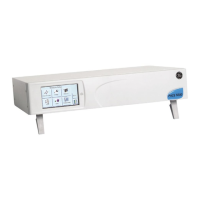
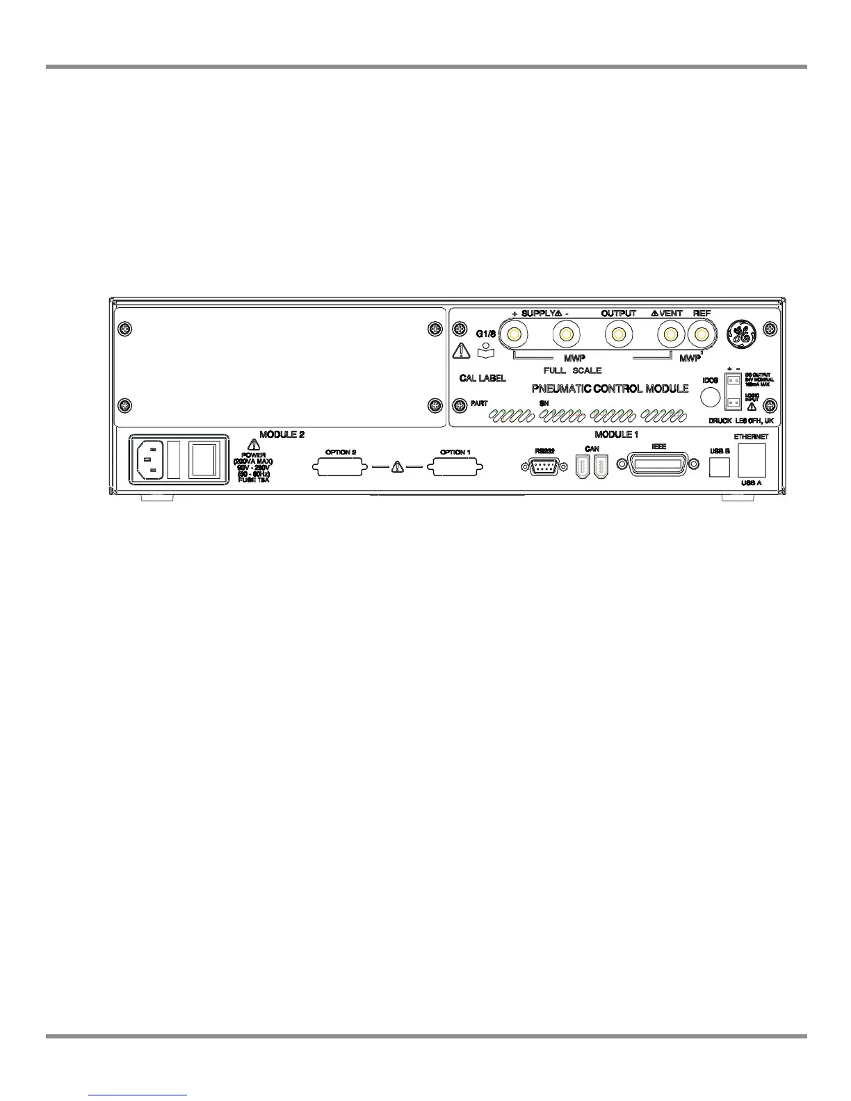
Figure 2-2, Pressure module rear view
Note: When using two pressure modules (Ref: Section 4.9, Pressure module replacement)
make sure that:
• The module with the highest pressure rating is fitted to the right hand side
Module 1 position as viewed from the rear of the product refer to (Ref: Fig 2-2)
• If two modules have the same pressure rating, make sure that the module with
the higher serial number is fitted to the right hand side Module 1 position as
viewed from the rear of the product.
Note: All pneumatic connections must comply with the Pressure Equipment Directive (PED)
or other regional pressure standards.
Note: When connecting the output ports of two pressure modules together make sure both
are either:
• below 70 bar
OR
• between 100 to 210 bar.
To prevent over-pressurisation of pneumatic parts and maintain compliance with the PED do
not mix categories.
 Loading...